C.2. Simulation Fidelity
The following sections cover the details of the simulation fidelity. At a high level the Virtual AEM is mostly a "pass through" driver, in that most commands are passed through to the underlying GARCs and GAFEs of the FREE board simulator.
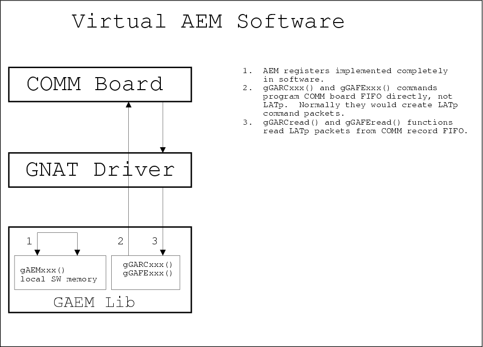
The commanding of the Virtual AEM registers is simulated in software, while the commanding of the GARC and GAFE registers is passed through to the FREE board as shown in Figure C-2.
The Virtual AEM supports the following features and functions of a real AEM:
AEM command/response including off-board GARC and GAFE registers.
AEM Event Triggering via software trigger.
AEM Event Read out.
Equally important is what the Virtual AEM does not support:
Semantics of AEM registers (except Trigger Sequencing Register).
External hardware triggers.
Multiple FREE board simulators.
C.2.1. Hardware Registers
All the registers of the AEM are simulated in exactly the same way with one important exception for the Trigger Sequencing Register (see below).
All registers can be written to without error.
On read all registers return a value of 0 – the read commands do not fail, but they always return a value of 0. The one exception is the Trigger Sequencing Register which returns it's current value as a 32-bit integer.
Attempting to read a non-existant register results in a TIMEOUT error.
C.2.2. Hardware Functionality
This section covers the fidelity of the simulation outside of command / response.
C.2.2.1. Reset
When the Virtual AEM decodes the dataless reset command the following occurrs:
All AEM register values are reset to zero.
The ACD_NRST line of the FREE is pulled to logic true, reseting the FREE.
C.2.2.2. Triggering
The Virtual AEM decodes a LAT trigger message and forwards an appropriately formed trigger command to the FREE.
C.2.2.2.1. Zero Suppression
If the zero suppression bit of the LAT trigger message is set then the Virtual AEM sends a "send only PHAs above threshold" trigger command to the FREE. If the zero suppression bit is clear then the Virtual AEM sends a "send all PHAs" trigger command to the FREE.
C.2.2.2.2. Calibration Sequence
The Virtual AEM simluates calibration trigger sequencing described in LAT Inter-module Communications and ACD Electronics Module ( see Background Documentation ). Read and understand the calibration trigger sequence before proceeding.
Did you read and understand the above documents? If not the following will not make much sense.
When the Virtual AEM decodes a LAT trigger message with the calStrobe bit set the Virtual AEM sends the dataless calibration command to the FREE. This does not result in an event readout.
If the TACK bit of the trigger message is also set then the Virtual AEM inserts a delay after the calibration command before sending the trigger command to the FREE. The Virtual AEM waits sysclk ticks times the current value of the TACK Delay of the Trigger Sequencing Register before sending the trigger command to the FREE. This results in an event readout.
C.2.2.3. Event Data
The real AEM is designed to aggregate the event contributions from 12 FREE boards. The Virtual AEM, however, can only have a single FREE board attached. For the purposes of the simulation the Virtual AEM uses the address of 0 (addresses range from 0 to 17) for addressing the FREE.
On event readout the Virtual AEM formats the single event contribution from the FREE into a complete AEM event as described in ACD Electronics Module. The Virtual AEM treats the single contribution as if it originated from the FREE board at address 0.