C.1. Hardware Setup
In the Virtual AEM setup a single LAT COMM I/O Board communicates directly with ACD's FREE electronics module as shown in Figure C-1.
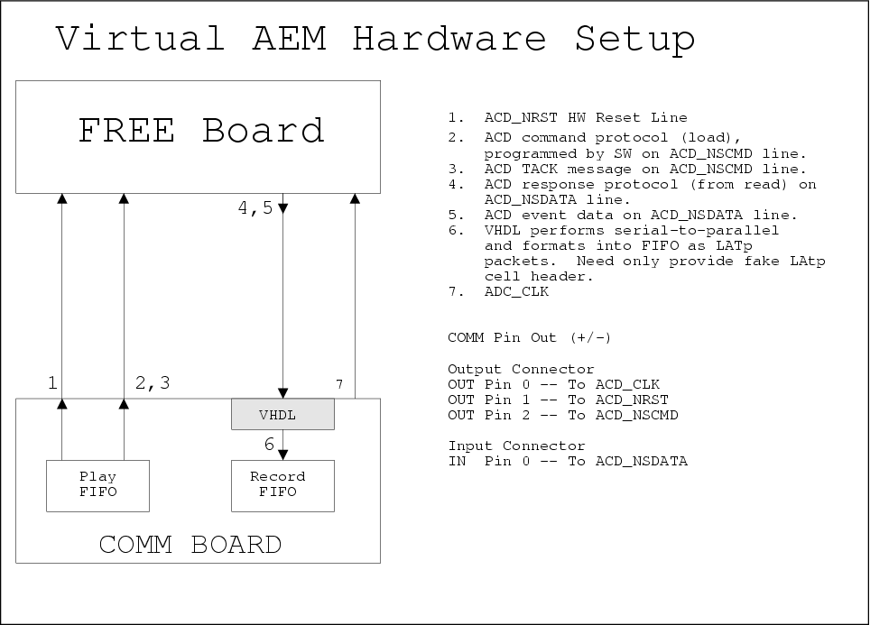
The FREE board requires 3 input signals and 1 output signal as shown in Figure C-1.
C.1.1. Required Hardware
A complete test stand for the Virtual AEM consists of the follow hardware:
1 LAT COMM I/O Board with firmware version 2.3 or later
1 FREE simulator board
1 customized cable, connecting COMM board and FREE board.
1 Motorola SBC
1 VME crate
1 I&T test stand PC workstation with SCL
C.1.2. Input Signals
The input signals consist of clock, reset and command signals labeled ACD_CLK, ACD_NRST and ACD_NSCMD respectively in Figure C-1.
 | The ACD_NSCMD signal is used for both commanding and triggering. |
The driver software will program these three input signals by loading the playback FIFO of the LAT COMM I/O Board appropriately. No additional hardware(VHDL) changes are necessary.
C.1.3. Output Signals
The single data output signal is labeled ACD_NSDATA in Figure C-1. This signal carries command response data and event read out data – we need a mechanism for differentiating these two forms of data.
We propose adding a new bit to an existing VME register ( perhaps the Options register ) called the "Virtual AEM Data Mode" bit. Software will program this bit according to what type of data is expected.
Software requests that the data on the ACD_NSDATA line be formatted by hardware in to LATp packets into the record FIFO of the LAT COMM I/O Board. See Figure A-1. This includes:
Recognize the start bit on ACD_NSDATA.
Add the cell announce and cell type bits to the record FIFO.
Add a dummy LATp cell header word to the record FIFO. Software does not care what the cell header content is so long as the cell header parity bit is correct.
Format the serial data stream from ACD_NSDATA into parallel 16-bit words in the record FIFO as cell payload. For response data the payload will fit in a single cell – for event data it will be necessary to span LATp cells. See Section C.1.3.1 and Section C.1.3.2 below.
For every cell calculate and set the cell truncate and cell parity bits correctly.
Upon reading a complete packet hardware will fire an interrupt.
C.1.3.1. Command Data
When set, the "Virtual AEM Data Mode" bit indicates that data arriving on ACD_NSDATA is in the format of a fixed length response to a command (see "ACD Front-End Electronics to AEM ICD", section 7.5.1) . The data length is 32 bits, including the start bit.
This data shall appear as 2 16-bit words in the cell payload.
C.1.3.2. Event Data
When clear, the "Virtual AEM Data Mode" bit indicates that variable length event data is expected on the ACD_NSDATA line. In this mode hardware will need to decode the "Zero Supression Bits" in order to determine the end of the event data ( see "ACD Front-End Electronics to AEM ICD", section 7.5.2). The event data consists of a fixed 39 bit header (including start bit) followed by 0 to 18 15-bit words, as determined by the number of bits set in the "Hit Map Bits".
The 39-bit header will be padded with 9 MBZ bits and stored as 3 16-bit words in the cell payload. Each 15-bit PHA value will be padded with 1 MBZ bit and stored as a 16-bit word in the cell payload.