LAT System Initialization
A Beginning
Curt Brune
GLAST Flight Software
| Revision History | ||
|---|---|---|
| Revision 0.1 | July 16, 2002 | |
- Table of Contents
- Introduction
- 1. Definitions
- 2. Assumptions
- 2.1. Hardware Assumptions
- 1. cPCI Crate Initialization
- 1.1. Configuring the Director SBC
- 1.2. Configuring the PCI Bus
- 1.3. Configuring and enabling the SIB
- 1.4. Configuring the Actor SBCs
- 1.5. Configuring the LCB
- 1.5.1. Configuring the Event Circular Buffers
- 1.5.2. Enabling the LCB
- 1.6. Memory Maps
- 1.6.1. SIB Memory Maps
- 1.6.2. LCB and SBC Memory Maps
- 1.7. LSI Timing Diagram
- Background Documentation
- List of Tables
- 1-1. SBC DMA spaces
- List of Figures
- 1. Layout of the PCI bus in a single cPCI crate.
- 1-1. Example LCB to PCI I/O Space Memory Map.
- 1-2. Example LCB to PCI Memory Space Memory Map.
- 1-3. Example NRL SBC to PCI I/O Space Memory Map.
- 1-4. Example NRL SBC to PCI Memory Space Memory Map.
- 1-5. Example PCI I/O Space Memory Map for single PCI crate.
- 1-6. Example PCI Memory Space Memory Map for single PCI crate.
- 1-7. Timing of PCI module configuration during PCI crate initialization
- 1-8. Timing of Actor SBC rebooting
Introduction
This document is intended to be a thought provoking straw man, which describes LAT System Initialization (LSI), with particular focus on configuring and initializing the hardware within the cPCI crates of the LAT. It aims to examine troublesome issues, but does not always identify solutions.
1. Definitions
The following definitions will apply throughout this document.
- LSI
LAT System Initialization
- SBC
Single Board Computer
- SIB
Spacecraft Interface Board
- LCB
PCI LAT Communications Board
- Director SBC
Used as a synonym for master SBC, but avoiding all the other meanings of the word master. Think Stanley Kubrick and "2001: A Space Odyssey". See definition of Actor SBC.
- Actor SBC
Used as a synonym for slave SBC, but avoiding all the other meanings of the word slave. Think "Kevin Spacey". See definition of Director.
2. Assumptions
This section covers working assumptions upon which this document depends.
2.1. Hardware Assumptions
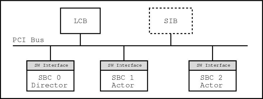
For the purposes of this document the hardware consists of one or more cPCI crates, each crate containing one and only one LCB desscribed in [2], one to three PowerPC SBCs described in [7] running VxWorks and optionally a SIB described in [1]. All communication between these PCI modules is performed via a 33 MHz PCI bus.
2.1.1. cPCI Backplane Assumptions
It is assumed that the PCI backplane is constructed is such a way that a SBC will be able to determine which physical slot it resides in. Most importantly it is assumed that a SBC will be able to determine whether or not it occupies the cPCI system slot.
2.1.2. SBC Assumptions
Much of how a SBC configures its memory spaces depends on the particulars of the board and the BSP. As the flight board is currently undetermined this chapter assumes a suitable board and BSP exists and that the VxWorks API for PCI communications is available.
The SBCs in the entire LAT are assumed to be homogeneous in both hardware and software. The only difference between the SBCs is in which cPCI slot a SBC resides. The Director SBC (or master) is defined as that SBC which resides in the cPCI system slot, while all other SBCs are defined as Actor SBCs (or slaves).
Homegeneity in hardware and software implies numerous properties of the system:
All SBCs will map the same local memory ranges to PCI address ranges.
The PCI-host bridge for each SBC will have the same PCI DeviceId and VendorId.
A simple diagram of this setup is shown below.
Chapter 1. cPCI Crate Initialization
This section summarizes the startup initialization of the LAT hardware for a single cPCI crate.
LAT System Initialization consists of the following activities, some of which ocurr simultaneously.
Initializing the Director SBC.
Configuring the PCI bus.
Configuring and enabling the SIB if present.
SBC Self-Configuration.
Configuring and enabling the LCB.
The bulk of the initialization consists of configuring various memory spaces for use with the PCI bus. For a good description of PCI memory spaces and the PCI architecture see [6].
The greatest challenge is communication and syncronization between the SBCs and the other cPCI modules before the system is completely configured – a classic boot strapping problem. Several recurring issues are:
How do the Actor SBCs know that the Director SBC has successfully completed configuring the PCI bus ?
How does the Director SBC know that the Actor SBCs have prepared themselves for event taking before enabling the LCB?
[ PLACEHOLDER – SIB issues here ]
1.1. Configuring the Director SBC
The Director SBC orchestrates the whole show. In order to do so it must first configure itself as the Director SBC.
A generic SBC can determine it is the Director SBC by probing which PCI slot it occupies. As stated previously the Director SBC will always reside in the cPCI system slot.
Once this determination is made the Director SBC proceeds to configure the other PCI modules, starting with the SIB if present.
1.2. Configuring the PCI Bus
The Director SBC is responsible for programming the Configuration space registers of each PCI module in the crate. It is important that only a single SBC, the Director SBC, perform this function – the Actor SBCs must wait for the Director SBC to finish configuring the PCI bus before accessing the LCB.
Configuring the PCI bus consists of defining the PCI memory spaces for each PCI module detected in the crate. In simple terms you can think of this as plug-n-play configuration.
When a PCI module is detected the Director SBC configures it by setting its Base Address Registers (BARs) and the Interrupt Pin located in the Configuration space of the PCI module.
Next the Director SBC enables the I/O space by programming the PCI Command register located in Configuration space.
1.2.1. Base Address Registers (BAR)
The BARs define the PCI addresses of the I/O and Memory spaces and also the size of each space. The size of each space is fixed by the VHDL of the PCI module, but the Director SBC programs the PCI address of each space. The addresses of these spaces is 32-bit aligned.
1.2.3. Command and Status Registers in PCI Configuration Space
The PCI configuration space Command register controls various properties of a PCI device including:
Enabling I/O space
Enabling Memory space
Enabling Bus Mastering
The PCI Status register also contains information about the outcome of recent PCI transactions. The Director SBC clears this register at the end of the configuration phase.
1.3. Configuring and enabling the SIB
During LAT System Initialization the most important objective is to establish communications with the ground as early as possible. To that end the SIB is configured immediately following the configuration of the Director SBC.
The exact configuration of the SIB is beyond the scope of this document, but at minimum the PCI bus configuration ( described in Section 1.2) for the SIB is performed at this point.
Subsequent to the PCI configuration of the SIB the Director SBC enables the SIB for business.
1.4. Configuring the Actor SBCs
Self configuration of the Actor SBCs occurs while the Director SBC is busy configuring the PCI bus and other PCI modules. As alluded to earlier the Actor SBCs must wait for the Director SBC to complete the configuration of the PCI bus before trying to use the LCB. A mechanism to do this is described in Section 1.5.2.
Each SBC requires access to a specific portion of the LCB PCI I/O and Memory spaces, see Section 1.6. In order to prevent the SBCs from mapping conflicting portions of the PCI memory space the SBCs must be enumerated. The SBCs are enumerated by using the slot position in the cPCI crate. The SBCs are enumerated in increasing order according to PCI slot position.
Given the opening assumption that the SBCs are homegeneous allows all the SBCs to map the PCI memory in a uniform fashion. Additionally this assumption allows the Director SBC to configure the LCB on behalf of the Actor SBCs, i.e. the Actor SBCs do not need to configure the LCB in order to enable the LCB. This significantly aids in the syncronization of the LCB and SBC configuration.
1.5. Configuring the LCB
The LCB exposes three different memory spaces to the PCI bus: Configuration space, I/O space and Memory space.
Only the Director SBC requires write access to the Configuration space of the LCB in order to set up the PCI memory space. On the other hand, all SBCs require read/write access to the I/O and Memory spaces of the LCB.
The tricky part is that the Actor SBCs cannot access the I/O and Memory spaces of the LCB until after the Director SBC configures the LCB.
1.5.1. Configuring the Event Circular Buffers
For event data the LCB maintains 3 circular buffers, one for each of the potential SBCs. See [2] for more details.
Since the SBCs are uniformly configured the Director SBC can program the base addresses of these circular buffers in the LCB's EVENTS_BASEn registers on behalf of the Actor SBCs. The Actor SBCs need not do this.
Once the circular buffers are confiugred the LCB is ready to be enabled.
1.5.2. Enabling the LCB
The Director SBC enables the LCB for business by setting two different bits in two different registers. First the PCI Memory space of the LCB is enabled by setting the Memory Access Enable bit of the PCI Configuration space Command register.
Next the Director SBC sets the Enable Event bit in the Control and Status register of the LCB. Setting this bit causes the LCB to place a special LCB Start marker word into the result FIFO of each SBC followed by an interrupt. This marker and interrupt is the signal that the LCB is now open for business.
An Actor SBC can syncronize itself with the enabling of the LCB as follows.
Check the Memory Access Enable bit of the PCI Configuration space Command register. If set then the LCB is configured and ready to go.
Otherwise the LCB is not yet configured so wait for the interrupt that is generated when the Enable Event bit in the Control and Status register of the LCB is set.
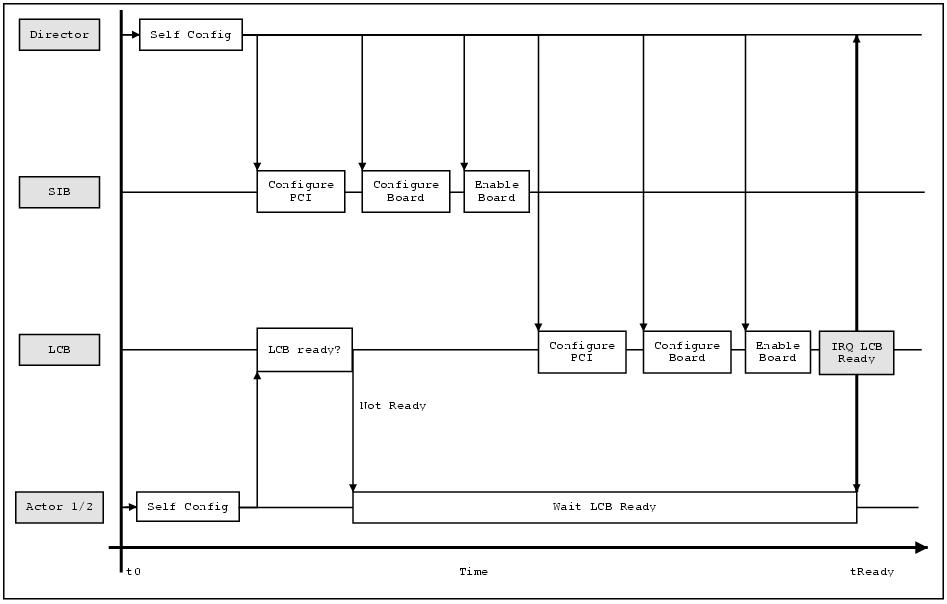
This scheme allows the Director SBC and the Actor SBCs syncronize in the case when the PCI crate first boots – all the SBCs are rebooted. The Actor SBCs would pend on the interrupt for syncronization in this case. See Figure 1-7 for a timing diagram describing this sequence.
This scheme also works in the case when a Actor SBC reboots in the middle of the day. In this case after booting the Actor SBC would look at the Memory Access Enable bit of the PCI Configuration space Command register, see it was set and assume the LCB is properly configured. See Figure 1-8 for a timing diagram describing this sequence.
1.6. Memory Maps
For an SBC to communicate with other PCI modules requires the mapping of several memory spaces over the PCI bus.
1.6.2. LCB and SBC Memory Maps
The LCB exposes its I/O space and Memory space to every SBC in the crate. In turn each SBC exposes some fraction of its physical memory to the LCB for DMA, including memory for event data, export lists and result lists.
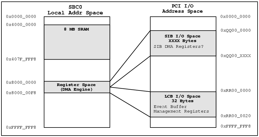
1.6.2.1. LCB Exposed Memory
The LCB exposes its I/O space and Memory space to every SBC in the crate. The I/O space allows the SBC and LCB to coordinate event memory usage. The Memory space allows the SBC and LCB to coordinate export and result lists. See [2] for more details.
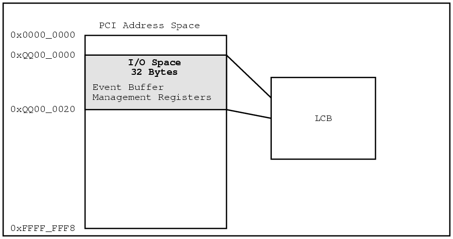
The PCI addresses of the I/O and Memory spaces is located in the BARs of the LCB. Both memory spaces must be mapped on a 32-bit boundry.
Sample memory maps for the I/O and Memory spaces of a LCB are shown below in Figure 1-1 and Figure 1-2 . The PCI addresses are for illustrative purposes only, as the actual addresses will be assigned by the Director SBC at system start.
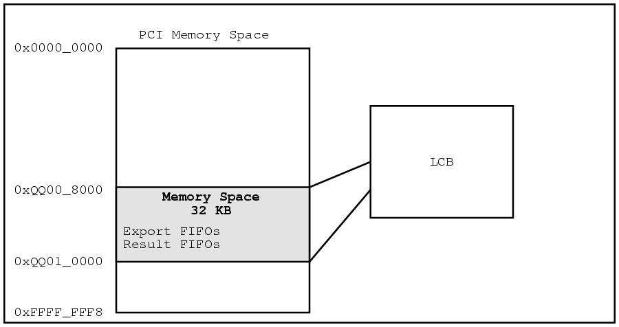
The mapping from PCI space to local address is handled by the PCI-host bridge of the SBC and/or memory controller. As the flight board is not yet determined the exact method for mapping memory is not currently known.
1.6.2.1.1. NRL Board Memory Mapping Details
The "NRL Board" uses a DMA engine to access the three types of PCI memory spaces. Programming the registers of the DMA engine allows access to the PCI Configuration, I/O and Memory spaces.
The registers of the DMA engine are located in the local memory space of the SBC at address 0x8000_0000.
The "NRL Board" does not use memory-mapped I/O to access the PCI memory spaces.
See [8] for more details.
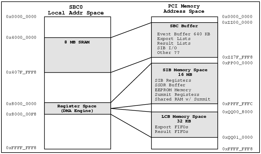
1.6.2.2. SBC Exposed Memory
Each SBC exposes three logical memory spaces to the DMA engine of the LCB – Event memory, Export List memory and Result List memory.
A SBC can only have one event memory space, but can have multiple export and result lists. The size, memory alignment and I/O operations for each space is shown below in Table 1-1.
| Memory Space | LCB DMA | Size | Alignment |
|---|---|---|---|
| Event | Write | 640 KB | 1 MB |
| Export List | Read | 4092 Bytes per List | 512 Byte |
| Result List | Write | 4084 Bytes per List | 8 Byte |
Table 1-1. SBC DMA spaces
As shown in Table 1-1 the LCB DMA engine writes to the event memory space, reads from the export list space and writes to result list space.
The mapping from PCI space to local address is handled by the PCI-host bridge of the SBC and/or memory controller. As the flight board is not yet determined the exact method for mapping memory is not currently known.
1.6.2.2.1. NRL Board Memory Mapping Details
The "NRL Board" can map 8MB of SRAM to the PCI address space. The 8MB block begins at local address 0x4000_0000. See [8] for more details.
Figure 1-3 below shows an example PCI I/O Space memory map for the "NRL Board" configured as the Director SBC. The PCI addresses shown are for illustrative purposes only.
Note the Director SBC has access to the PCI I/O Space for both the SIB and LCB. An Actor SBC, on the other hand, would only have access to the PCI I/O Space of the LCB.
Figure 1-4 below shows an example PCI Memory Space memory map for the "NRL Board" configured as the Director SBC. The PCI addresses shown are for illustrative purposes only.
Note the Director SBC has access to the PCI Memory Space for both the SIB and LCB. An Actor SBC, on the other hand, would only have access to the PCI Memory Space of the LCB.
1.6.2.3. Putting It All Together
Figure 1-5 below is a sample PCI I/O Space Memory Map for an entire PCI crate, including three SBCs, a LCB and a SIB. The SBCs are assumed to be "NRL Board"s. The PCI addresses shown are for illustrative purposes only.
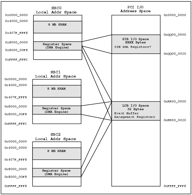
Note the Director SBC has access to the PCI I/O Space for both the SIB and LCB. The Actor SBCs, on the other hand, only have access to the PCI I/O Space of the LCB.
Figure 1-6 below is a sample PCI Memory Space Memory Map for an entire PCI crate, including three SBCs, a LCB and a SIB. The SBCs are assumed to be "NRL Board"s. The PCI addresses shown are for illustrative purposes only.
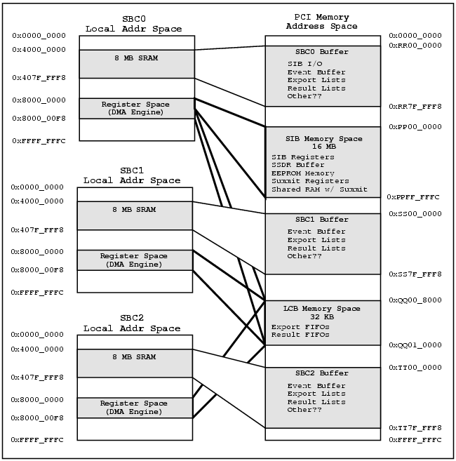
Note the Director SBC has access to the PCI Memory Space for both the SIB and LCB. The Actor SBCs, on the other hand, only have access to the PCI Memory Space of the LCB.
1.7. LSI Timing Diagram
The sequencing described in the previous sections is presented here as timing diagrams.
1.7.1. PCI Crate Initialization Timing Diagram
The sequencing of PCI module initialization during PCI crate initialization is shown below. Note the Actor SBC wait for the "LCB Ready IRQ" before accessing the LCB.
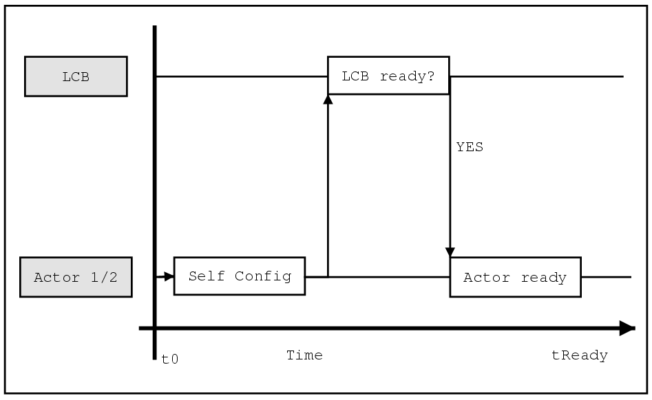
1.7.2. Single Actor SBC Reboot Timing Diagram
The rebooting of a single Actor SBC is shown below in Figure 1-8. This covers the case when the PCI crate is previously configured, but one of the Actor SBC is rebooted. In this case the LCB is already configured when the Actor SBC reboots.
The Actor SBC determines the LCB is already configured by reading the Memory Access Enable bit of the PCI Configuration space Command register. In this case the Actor SBC can proceed to use the LCB without waiting.