LAT Communication Board Driver
Software Architecture and Interfaces
Curt Brune
GLAST LAT Flight Software
March 17, 2003
| Revision History | ||
|---|---|---|
| Revision 0.5 | 03-17-2003 | |
| Revision 0.4 | 01-21-2003 | |
| Revision 0.3 | July 25, 2002 | |
| Revision 0.2 | July 18, 2002 | |
| Revision 0.1 | July 11, 2002 | |
- Table of Contents
- Introduction
- 1. LCB Primer
- 2. LCBD Overview
- 1. Hardware Interface Driver
- 1.1. External Library Dependencies
- 1.2. Register Model
- 1.2.1. PCI Configuration Space Registers
- 1.2.2. PCI I/O Space Registers
- 1.2.3. PCI Memory Space Registers
- 1.3. Initialization and Configuration
- 1.3.1. Initialization
- 1.3.2. Default Configuration
- 1.4. LCB Statistics
- 1.4.1. Hardware Statistics
- 1.4.2. LATp I/O Statistics
- 2. Interrupt Mode Driver
- 2.1. Driver Libraries
- 2.2. Overview of Operation
- 2.3. Result Dispatch
- 2.3.1. Command/Response Data
- 2.3.2. Unsolicited Data
- 2.4. Command/Response Interface
- 2.5. Unsolicited Data Interfaces
- 2.5.1. Registering Call Back Handlers
- 2.5.2. Navigating Unsolicited Data
- 2.5.3. Freeing Unsolicited Data
- 2.5.4. Example Handlers
- 3. Polled Mode Driver
- 3.1. Driver Libraries
- 3.2. Driver Interface
- 3.2.1. Driver Initialization
- 3.2.2. Dispatching Results
- 3.2.3. Sending Bulk Data
- 3.3. Example Driver
- 3.3.1. Initialization
- 3.3.2. Polled Event Loop
- 3.3.3. Sending Bulk Data
- References
- List of Tables
- 2-1. LIOX Handle States
- 2-2. LIOX List Memory Attributes
- 2-3. Deallocating Memory
- 3-1. polled mode LCBD Memory Attributes
- List of Examples
- 2-1. Reading A Calorimeter DAC
- 2-2. Reading a Calorimeter DAC – Continued
- 2-3. Read Calorimeter DAC – Synchronous Interface
Introduction
This document describes the software architecture and interfaces of the LCB Driver (LCBD). The LCBD consists of a low-level hardware driver for the PCI LAT Communications Board (LCB)[1] and a high-level external Application Programming Interface (API). The low-level hardware driver is used internally by LCBD to implement the external APIs. User software will only access the LCB through the external APIs.
1. LCB Primer
Communication within the LAT is provided by the LCB, a cPCI module residing in every cPCI crate within the LAT. A LCB can communicate directly with other LCBs (in other crates) on the event fabric or with other LATp nodes on the LAT's command/response fabric [huffer2].
The LCB manages traffic on the Command/Response fabric and the Event Data fabric. With the Command/Response fabric a node can issue a command to another LATp node and receive the solicited response. For example, this is used to read a register on a remote electronics module. The key point is the response is solicited, so it is expected to arrive.
Event data, however, arrives unsolicited, i.e. whenever it is ready. A special case of "event data" is the unsolicited LCB-to-LCB communication, which is also unsolicited. In either case a handler is is notified and proceeds to processes the unsolicited data in a timely manner.
2. LCBD Overview
The LCBD provides high-level external APIs to the user for managing the LCB:
Initialization, Configuration and Statistics
Command/Response Data
Unsolicited Event Data
Unsolicited LCB-to-LCB Data
Polled mode operations during EPU boot
These high-level APIs will remain constant even as the underlying hardware matures from the prototype to the final production version.
The LCBD also includes a low-level hardware interface to the LCB. This interface, however, is not exposed directly to the end user. It is used internally by LCBD to implement the external APIs.
The hardware interface provides basic initialization and configuration services, including simple access to the LCB's PCI register model. This interface is expected to evolve as the LCB hardware and firmware matures.
Chapter 1. Hardware Interface Driver
The hardware interface driver supports low-level services of the LCB, including:
Access to the LCB PCI registers.
Initialization and configuration routines.
LCB Statistics.
The hardware interface is intended to be a private interface used by LCBD to support the high-level public interface. However, the hardware engineer designing and implementing the LCB may also find the hardware interface useful for debugging purposes.
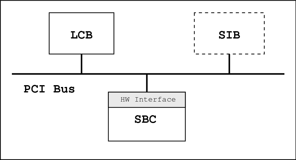
A diagram of the cPCI crate and PCI bus is shown in Figure 1-1. This diagram shows the relationship between the single board computer (SBC), the hardware interface, the PCI bus and the LCB.
1.1. External Library Dependencies
The hardware interface depends on the VxWorks RTOS for low level PCI services, including PCI auto-detection and access to the PCI Configuration Memory Space.
How to handle this dependency when the RTOS is unavailable during bootstrap is TBD.
1.2. Register Model
The LCB has registers in the three PCI memory spaces: Configuration, Memory and I/O. See [huffer1] for a complete list of these registers. The LCBD hardware interface will provide read/write access to these registers and in certain cases access to fields within registers.
1.2.1. PCI Configuration Space Registers
The PCI configuration space registers are used to identify and locate the LCB on the PCI bus. Once the LCB is located the configuration space registers are used to configure the PCI memory locations for the I/O Space and the Memory Space.
The PCI configuration space registers are manipulated on long word(32 bit), word(16 bit) or byte(8 bit) boundaries at byte offsets from the beginning on the configuration space. Word in/out routines are shown below:
1.2.2. PCI I/O Space Registers
The PCI I/O space registers are all 32-bit registers. These registers control various aspects of the LCB, including LATp parameters, resets, test features and event data taking.
All registers have 32-bit read/write interface functions. Some registers also have read/write functions for accessing register sub-fields.
1.2.2.1. Control and Status Register (CSR)
The 32-bit Read/Write functions for the CSR are shown below.
The 32-bit CSR has multiple sub-fields controlling various operations of the LCB. The hardware interfaces for the CSR sub-fields are shown next.
// Read/Write of RESET bit |
int LCB_IO_CSR_Reset(LCB *lcb);
int LCB_IO_CSR_Reset_Read(LCB *lcb, unsigned short *rst);
// Read/Write of Event Enable bit |
int LCB_IO_CSR_EventEnable_Write(LCB *lcb, unsigned short val);
int LCB_IO_CSR_EventEnable_Read(LCB *lcb, unsigned short *val);
// Read/Write of Event Path Select bit |
int LCB_IO_CSR_EventPath_Write(LCB *lcb, unsigned short val);
int LCB_IO_CSR_EventPath_Read(LCB *lcb, unsigned short *val);
// Read/Write of Command Path Select bit |
int LCB_IO_CSR_CmdPath_Write(LCB *lcb, unsigned short val);
int LCB_IO_CSR_CmdPath_Read(LCB *lcb, unsigned short *val);
// Read/Write of Header Parity Definition Select bit |
int LCB_IO_CSR_HdrParity_Write(LCB *lcb, unsigned short val);
int LCB_IO_CSR_HdrParity_Read(LCB *lcb, unsigned short *val);
// Read/Write of Payload Parity Definition Select bit |
int LCB_IO_CSR_PayloadParity_Write(LCB *lcb, unsigned short val);
int LCB_IO_CSR_PayloadParity_Read(LCB *lcb, unsigned short *val);
// Read/Write of Inhibit Pending Event bit |
int LCB_IO_CSR_InhibitPendEvt_Write(LCB *lcb, unsigned short val);
int LCB_IO_CSR_InhibitPendEvt_Read(LCB *lcb, unsigned short *val);
1.2.2.2. FIFO Faults Register
The FIFO Faults register latches any read or write faults for the internal FIFOs of the LCB. Writing this register clears any and all latched status.
1.2.2.3. EVENTS_BASE and EVENTS_FREE Registers
The EVENTS_BASE and EVENTS_FREE registers help manage the circular buffer used for event data. The EVENTS_BASE register defines the origin of the circular buffer, while the EVENTS_FREE register maintains the "read pointer" for the circular buffer. The "write pointer" is maintained internally by the LCB.
1.2.3. PCI Memory Space Registers
The LCB's PCI Memory Space provides access to the export and result FIFOs, which are used to send and receive data. These FIFOs are 32-bits wide and 1024 entries deep, holding a total of 4KB.
When sending data a 32-bit export descriptor is written to the export FIFO. This descriptor defines where the data to be sent resides.
When receiving data a 32-bit result descriptor is read from the result FIFO. This descriptor defines where the received data resides.
The use of these FIFOs is fully described in Chapter 2. The interface functions are shown below.
1.3. Initialization and Configuration
Before using the LCB it must first be configured for a particular task. Before configuring, however, the board must first be initialized.
1.3.1. Initialization
Initialization refers to the set of required operations necessary to put the LCB into a functioning, well known state. These operations include:
Interface Allocation
Board Discovery
Default Configuration
1.3.1.1. Interface Allocation
The LCBD hardware interface is managed using an opaque handle, whose type is pointer to struct _LCB. All of the hardware interface functions use the members of struct _LCB to access the underlying hardware.
Before initializing the LCB, memory must first be allocated for the opaque handle. The LCB_sizeOf() function returns the size of struct _LCB, allowing the higher level interface to manage memory allocation.
A simple-minded example using malloc() is shown below:
typedef struct _LCB LCB; LCB *lcb; lcb = (LCB *)malloc(LCB_sizeOf()); |
1.3.1.2. Board Discovery
Board discovery refers to the process of detecting the LCB within the cPCI crate. Once detected various parameters about the LCB are stored in the opaque handle previously allocated. Examples of parameters include the memory mapped locations of the PCI I/O Space and PCI Memory Space. These parameters are used by subsequent calls to the hardware interface in order to access registers.
The LCB_boardDetect() function attempts to detect a LCB. If successful this routine stores the associated parameters in the opaque handle lcb.
An example of detecting the LCB is shown below:
if ( LCB_boardDetect(lcb) != LCB_OK) {
   // bad things
}
else {
   // access hardware with lcb handle
}
|
1.3.2. Default Configuration
The hardware interface is also responsible for leaving the LCB in a default, well known state after initialization. The default state requires programming of PCI Configuration Space registers and PCI I/O Space registers.
1.3.2.1. PCI Configuration Space Registers
The Command and Interrupt Control/Status registers require special handling for the default configuration.
For the Command register the settings are:
PCI I/O Space Enabled
PCI Memory Space Enabled
Bus Master Enabled
For the Interrupt Control/Status register the settings are:
PCI Interrupts Disabled
1.3.2.2. PCI I/O Space Registers
Setting the default configuration requires setting the CSR (Section 1.2.2.1).
For the CSR the settings are:
Unsolicited Data Disabled
Event Path A Selected
Command Path A Selected
Odd Header Parity
Odd Payload Parity
Pending Events FIFO Enabled
For the PMR the settings are TBD.
1.4. LCB Statistics
The LCBD maintains several different counters for various events that occur at the driver level. For each type of counter the LCBD provides an interface for retrieving the counter and for clearing the counter.
1.4.1. Hardware Statistics
The LCBD will maintain a count of the number of interrupts received. The interface to this counter is shown below:
In addition the LCB defines four PCI/DMA errors that can occur. The LCBD maintains 16-bit counters for each of the possible error types and provides an interface for retrieving and clearing these counters. These functions are shown below.
int LCB_getErrCount(LCB *lcb, LCB_ErrorType err, unsigned short *count);
int LCB_clearErrCount(LCB *lcb, LATp_ErrorType err);
The LCB_ErrorType parameter is an enumerated type having four possible values, one for each of the four possible error types. The possible errors are:
DMA of export list failed
DMA of result list failed
DMA of event failed
Allocation of event data failed
1.4.2. LATp I/O Statistics
LATp defines 16-bit transmitter statistics and receiver statistics for all nodes on a fabric [huffer2]. The LCBD maintains these statistics for the LCB's communications on the command/response fabric and the event fabric. Functions for retrieving and clearing these statistics are declared below.
int LCB_getStats(LCB *lcb, LATp_FABRIC fabric, unsigned short *rx_Stats, unsigned short *tx_Stats);
int LCB_clearStats(LCB *lcb, LATp_FABRIC fabric);
The fabric parameter is an enumerated type having two possible values, one for each of the two fabrics the LCB supports.
Chapter 2. Interrupt Mode Driver
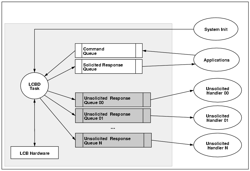
The Figure 2-1 below shows the software architecture for the interrupt mode LCB driver.
2.1. Driver Libraries
The LCBD interface presents a public, stable interface to multiple users. All user applications communicate via the LCBD interface. The LCBD interface, in turn depends on the low level hardware interface (Chapter 1) and on several utility services provided by a common LAT Flight Software utility library[2].
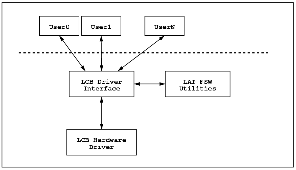
The Figure 2-2 below shows the interrupt mode LCB driver library and its dependencies. Note that the user applications only interact with the public interface of the LCBD.
The LCBD will use the following services from the LAT FSW utility library:
LAT FSW Utility Services
- Message Queues
The LCBD relies on message queues to buffer communications between the hardware and the user applications[3]. This includes messages sent from the user application (commands) and messages sent from the LCB (responses or unsolicited data).
- Time and Timers
The LCBD will need wake up timers in order to timeout commands whose responses either never arrive or arrive late.
- Fixed Packet Allocators
The LCBD will need to manage a pool of LCB_msg objects, which are all fixed length. These messages are allocated by the LCBD and are freed by user supplied result processing functions.
2.2. Overview of Operation
The LCBD provides the following services:
Dispatching solicited and unsolicited response packets to user supplied handling routines.
Sending packets on the LATp command fabric.
Receiving solicited packets on the LATp response fabric, i.e. receive the responses from commands.
Injecting timed markers into the results FIFO.
Resetting the LATp command fabric.
Sending unsolicited packets on the LATp event fabric, the so called LCB-to-LCB data.
Receiving unsolicited packets on the LATp event fabric, including event data and LCB-to-LCB data.
2.3. Result Dispatch
All LCB result descriptors for both unsolicited data and command/response data are stored in the same LCB Result Descriptor FIFO. When the FIFO goes from empty to non-empty the LCB raises an interrupt signal.
A block diagram of the result dispatch ISR is shown below.
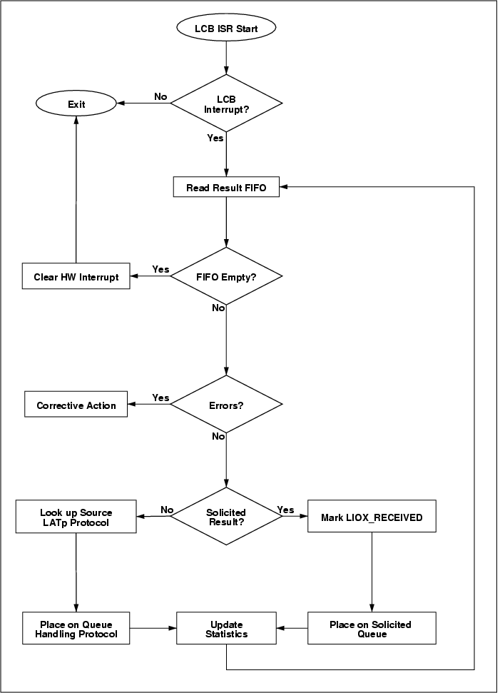
The ISR servicing this interrupt will read the result descriptor FIFO until empty, sorting the descriptors based on the "unsolicited" bit in the result descriptor.
2.3.1. Command/Response Data
Once it is determined that the result descriptor is for command/response the corresponding LIOX is located. For more about the LIOX see Section 2.4.1 and Figure 2-4.
The state of the received LIOX is next changed from the LIOX_PEND state to the LIOX_RECEIVED state.
Command/response data will be given a higher priority when servicing result descriptors since it is assumed that command/response data is relatively rare compared to unsolicited data. This means the solicited message queue will have a higher priority than the unsolicited queues.
An LCB_msg object containing the result descriptor and LIOX handle will be placed on the Solicited Response Queue, allowing the processing of the cmd/rsp result to occur at task level. A task reading the message queue will call back the user supplied result processing function passing the LIOX handle and any user data as arguments.
2.3.2. Unsolicited Data
The unsolicited data can take many forms, including raw event data from event builders, filtered event data from event processing units, housekeeping data and other arbitrary data. The type of the unsolicited data, however, cannot be determined by the result descriptor alone – the LCBD will dispatch all unsolicited result descriptors based on the source packet's LATp protocol field.
LATp defines 4 protocol types [huffer2]. The LATp cell header defines the protocol type as a 2-bit field. One of the protocol types is unavailable for dispatching, leaving 3 protocols for user dispatch.
Previously (see Section 2.5) the user registered call back routines for the various LATp protocol types. The LCBD queues the unsolicited message to the queue handling a specific LATp protocol type or to the default queue if no handler is registered.
It is the responsibility of the user application on the consuming end of the message queue to process the message in a timely manner and return the unsolicited data memory to the circular buffer as described in Section 2.5.
2.4. Command/Response Interface
This section describes the sending of commands and the processing of results with the LCBD. Commands are bit sequences sent down to the front end electronics (register reads, register writes and dataless commands ). Every command generates a result – register writes and dataless commands generate a simple "command successfully transmitted" result, while register read commands return the register value as a result.
Some definitions used within this section:
- Command Item or simply Command
A single command sent to the front end electronics.
- Command List
An ordered list of command items containing one or more command items.
- Result Item or simply Result
A single result from the LCB in reply to a command item.
- Result List
An ordered list of result items from the LCB in reply to a command list.
- LAT I/O Transaction
An indivisible unit of work consisting of a command list and its associated result list.
The LCB has the capability of bundling several command items together and sending them sequentially as a command list. After all the commands are processed and all the responses are received the LCB fires an interrupt that the driver traps. The driver then notifies the user – see Section 2.3 for more details.
This arrangement allows for asynchronous commanding, e.g. a user can queue a command list to the LCB, continue to do other work and then be notified asynchronously that the results are ready for processing.
For the case when a user only wants to send a single command it is purposed to also offer a synchronous interface to the LCBD. With this interface a user would queue a single command to the LCB and wait for the command to complete. At this time it appears straight forward to build the synchronous interface on top of the asynchronous interface.
2.4.1. Asynchronous Command and Response Interface
The asynchronous interface offers a powerful way for users to queue command lists to the LCB for processing. While the LCB is busy processing the command list and receiving result items the user can continue to do other work. The LCBD notifies the user after the final command item and result item are processed (see Section 2.3). After notification the user would proceed to inspect the result list.
The LCBD provides a data structure for organizing the command list and the result list called the LAT I/O Transaction (LIOX). Users communicate with the LCBD via an opaque handle to a LIOX structure. A diagram showing the relationship between the command list, result list and LIOX structure is shown below in Figure 2-4.
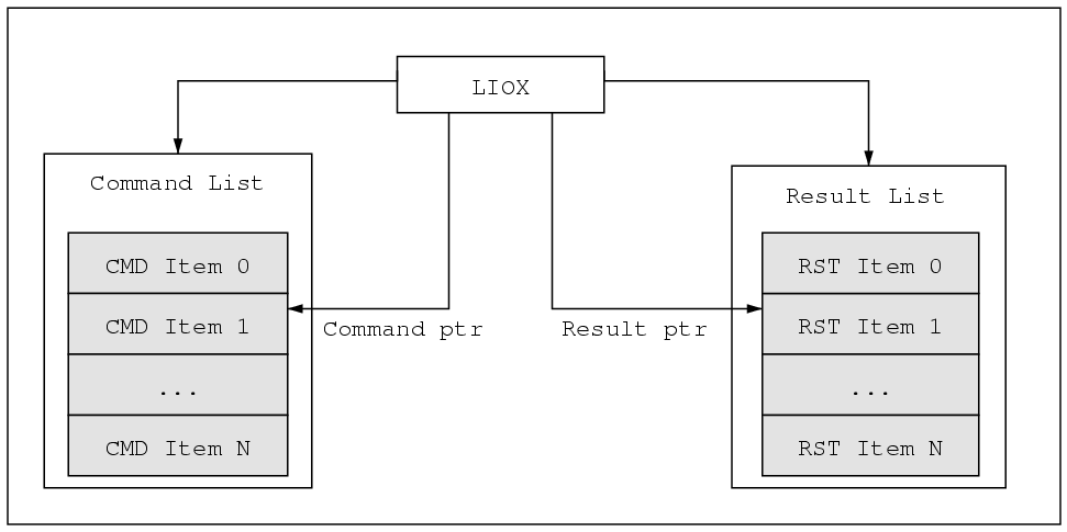
In addition to organizing memory the LIOX also maintains an internal command pointer used when filling the command list. The command pointer behaves much like a file pointer – it always points to the memory location where the next command will be inserted. As commands are added to the command list the command pointer is updated to point to the next available command slot.
The LIOX also performs bounds checking, i.e. it will not allow more commands to be added than will fit into the available memory for the command list.
2.4.1.1. Preparing for Commanding
Before creating and sending command lists via the LCBD a LIOX handle must first be properly initialized. This entails the following activities:
Allocate memory for the LIOX structure, the command list and the result list.
Implement a user-defined result processing function called during result dispatch (see Section 2.3).
Initialize the LIOX by passing in pointers for the command list memory, for the result list memory and for the result processing function.
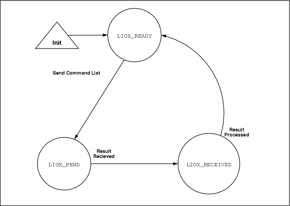
Once created a LIOX handle can be in one of the following states:
| LIOX State | Description |
|---|---|
| LIOX_READY | Allocated, ready for transmission |
| LIOX_PEND | Command list sent, waiting for result |
| LIOX_RECEIVED | Result received |
Table 2-1. LIOX Handle States
The allowable state transitions are shown below in Figure 2-5. These states are discussed in the following sections.
2.4.1.1.1. Memory Allocation
Memory allocation is left entirely to the user, i.e. the LCBD never allocates memory of its own. Memory must be allocated for the LIOX handle, the command list and the result list.
The LCB places constraints on the memory allocated for command lists and result lists. In particular the memory for the lists must be visible to the PCI bus and have the size and alignment attributes shown in Table 2-2.
| Memory Space | LCB DMA | Size | Alignment |
|---|---|---|---|
| LIOX Handle | N/A | < 100 Bytes, fixed. | None |
| Command List | Read | Up to 4092 Bytes | 512 Byte |
| Result List | Write | Up to 4084 Bytes | 8 Byte |
Table 2-2. LIOX List Memory Attributes
All of the above objects could be pre-allocated to form object pools. The user could request an object from the object pool as needed.
The number of allocated lists is a function of the number of :
Concurrently executing command lists, e.g. background housekeeping during other commanding.
Command lists previously prepared, e.g. command lists containing default/baseline configuration commands.
It will be worthwhile for the LAT system software to offer memory allocators for different alignment requirements. These allocators could be part of the LAT FSW utility library.
After a result is received and the result is processed the user can return the objects to the appropriate object pool. Objects can be safely deallocated according to the following table:
| Object | LIOX States OK to Deallocate |
|---|---|
| LIOX Handle | LIOX_READY, LIOX_RECEIVED |
| Command List | LIOX_READY, LIOX_RECEIVED |
| Result List | LIOX_READY, LIOX_RECEIVED |
Table 2-3. Deallocating Memory
It is unsafe to deallocate memory when the LIOX state is LIOX_PEND. The LCB will DMA the result into the result list whenever the result arrives. Once a LIOX is initiated the LCB "owns" the result list and command list memory until the transaction completes.
This means we cannot safely deallocate the memory for the result list or the command list until the transaction completes – if the transaction never completes we lose the memory associated with both lists and the memory for the LIOX handle.
2.4.1.1.2. Initializing a LIOX Handle
Initializing a LIOX handle requires the following steps:
Allocate memory for the LIOX handle.
Allocate memory for the command list.
Declare the response handling function.
Allocate memory for the result list (optional).
Allocating memory for the result list may be deferred until the command list is completely loaded, at which time the total amount of memory required for the result list is known. If, however, the LIOX will be used for synchronous operations ( see Section 2.4.2) the result memory must be supplied at initialization time.
The function prototypes for the response handling function and the initialization function appear below:
int LIOX_Init(LIOXHandle lh, unsigned short cmdLen, unsigned int *cmdList, unsigned short rspLen, unsigned int *rspList, LCB_resultFunc func, void *usrData);
The following pseudo-code illustrates the initialization of a LIOX Handle.
// declare result processing callback and extra data
static   int myProcessResultFunc( LIOX lh, void *userData);
unsigned int myExtraData;

// allocate memory for command list and LIOX struct
void            *pCmdList; // command list
void               *pLIOX; // LIOX    handle
unsigned  short    cmdLen; // command list length
LIOXHandle             lh;

// allocate memory for the command list -- suitably aligned
cmdLen = 4080;
pCmdList = mallocCommandList( cmdLen);

// allocate memory for the LIOX structure
pLIOX = mallocLIOX( LIOX_SizeOfIOX());

// create opaque handle to LIOX -- note the result list length
// is zero and the result list pointer is NULL.  These will be
// provided later when the command list is queued.
lh = LIOX_Init( pLIOX,
                cmdLen, pCmdList,
                0, NULL,
                myProcessResultFunc,
                myExtraData);

// LIOXHandle lh is now initialized and ready for use
|
The allocation of the result list memory is deferred until after the command list is completely filled. At that time the required size of the result list is completely determined and the exact amount of memory can be allocated. See Section 2.4.1.3.
After the LIOX handle is initialized the internal command pointer points to the first available command slot in the command list. A mechanism exists for reseting the command pointer so that a LIOX handle can be re-filled with a new list of commands.
2.4.1.2. Adding Commands to the Command List
Commands are added to the command list by passing the associated LIOX handle as an argument to the family of "LAT Command Functions". The "LAT Command Functions" provide a basic interface for read/write and dataless commands to the various addressable objects within the LAT.
As of this writing 11 types of addressable objects exist within the LAT – this number is expected to grow to about 20 types of objects. Each object contains registers which are also addressable. The following object types exist today:
TEM Common Controller
TEM Trigger Interface Controller (GTIC)
Tracker Cable Controller (GTCC)
Tracker Readout Controller (GTRC)
Tracker Front End Controller (GTFE)
Calorimeter Cable Controller (GCCC)
Calorimeter Readout Controller (GCRC)
Calorimeter Front End Controller (GCFE)
AEM Common Controller
ACD Readout Controller (GARC)
ACD Front End Controller (GAFE)
For each object type there exists three "Command Functions" – register load, register read and dataless command. That is a total of 33 functions for 11 object types. A rough estimate projects 50-60 functions ( about 20 object types ) in the final system.
In addition to the above command/response items are three special command items:
Command Fabric Reset
Injected Time Markers
Sending bulk data on the event fabric
2.4.1.2.1. Normal Command Items
The following illustrates the queueing of a normal command item.
Example 2-1. Reading A Calorimeter DAC
As an example consider the hypothetical case of reading a DAC on a calorimeter front end chip (GCFE). The reading of a DAC register corresponds to a register read "Command Function". To uniquely address a DAC register on a specific GCFE requires a TEM address, a GCCC address, a GCRC address, a GCFE address and the DAC register number. The GCFE read "Command Function" requires all these parameters as arguments. Below is the function prototype for LIOX_qGCFEload.
int LIOX_qGCFEread(LIOXHandle lh, unsigned short temId, unsigned short gcccId, unsigned short gcrcId, unsigned short gcfeId, unsigned short regId);
Calling LIOX_qGCFEread with appropriate arguments would add a GCFE read command to the command list of the LIOX handle. The LIOX handle would update its internal command pointer to point at the next available command slot in the list. An example is shown below:
unsigned int errVal; LIOXHandle lh; /* previously initialized */ /* queue the read command to the command list */ errVal = LIOX_qGCFEread( lh, temId, gcccId, gcrcId, gcfeId, DACregId); |
This process is repeated, adding commands to the LIOX handle until the entire command sequence is loaded or the LIOX handle runs out of memory. Next the command list is queued to the LCB for execution.
2.4.1.2.2. Command Fabric Reset
A special command item exists that instructs the LCB to assert the hardware reset line of the command fabric. This resets all the nodes of the command fabric. This command generates a result item that will have the reset field of the error word set.
The fabric reset command must be the only command in the command list – queueing the fabric reset command will erase any previously entered command items in the command list. This is because the fabric reset command is implemented as a null command list of zero length.
2.4.1.2.3. Injected Time Markers
Quoting [huffer1]:
An application may need to specify an arbitrary amount of idle time between two export items, or to inject an accurate time marker in the RESULTS FIFO. Both of these requirements must be satisfied without actually transmitting a packet on a fabric ... A result is generated at a time determined by the stall/timeout field.
Queueing an injected marker command item takes the following form:
The stall/timeout is in units of sysclks, i.e. 50 nano-second increments.
Unlike the fabric reset, multiple markers may be queued per command list.
This command generates a result item when completed.
2.4.1.2.4. Sending Bulk Data on the Event Fabric
While the sending of bulk data occurs on the event fabric, the mechanism for queueing a bulk transfer looks like queueing a command item. Queueing a bulk LCB-to-LCB data transfer takes the following form:
int LIOX_qBulk(LIOXHandle lh, unsigned short nodeId, unsigned short proto, unsigned int nBytes, unsigned int *data);
For LCB-to-LCB the MSB of the 6-bit nodeId must be set, i.e. all LCBs have a nodeId with the high-order bit set. LIOX_qBulk() will fail if the nodeId is not of the proper format.
The proto parameter indicates which of the 3 LATp protocols to use.
Multiple bulk transfers may be queued in the same command list.
This command generates a result item when completed.
2.4.1.3. Executing a Command List
Once the command list of a LIOX handle is loaded the list is ready for execution. At this time the amount of result list memory required is completely determined by the command items. The result list memory is now allocated and assigned to the LIOX handle.
The LIOX_resultSize() function returns the number of bytes required for the result list. The result list memory must be suitably aligned as described in Table 2-2. The result list memory is added and the command list queued with a single call to LIOX_qCmdList().
int LIOX_resultSize(LIOXHandle lh);
int LIOX_qCmdList(LIOXHandle lh, unsigned short nBytes, unsigned int *rstList);
Behind the scenes, however, the LCBD performs various bookkeeping operations when queueing the command list. Refer to [huffer1] for more details on queueing command lists (referred to as export lists).
The address of the command list and the length of the command list are queued to the LCB by the LCBD. Together the length and address are called the export descriptor. The length of the list is calculated from the internal command pointer.
Once queued the state of the LIOX transitions from LIOX_READY to LIOX_PEND. Refer to Figure 2-5.
After queueing the export descriptor the LCB takes over. The LCB DMAs the command list from the SBC's memory to the LCB's memory and sends the commands out on the command/response fabric of the LAT one by one.
As the results come into the LCB it stores the result items locally. After the final result comes in the LCB DMAs all the result items to the result list associated with the command list that initiated the commanding sequence. It next puts a result descriptor in the result FIFO and fires an interrupt (if the FIFO transitions from empty to non-empty).
The LCBD traps the interrupt and reads the result descriptor from the results FIFO. The LCBD passes the result descriptor into the result dispatch unit (see Section 2.3) for routing to the appropriate message queue.
2.4.1.4. Processing Results
Once a result list is ready the LCBD queues a LIOX handle to the Solicited Response Queue (see Figure 2-1). Ultimately this results in a callback to the user supplied solicited response handler.
Using the LIOX handle the user navigates and processes the result list. When processing is complete the user may free the LIOX handle and the associated command list and response list.
The LCB provides two types of result items, both of which are fixed in length. The first type of result item is a simple "transmission verification" result used for command items, which by their nature have no response data. This result type contains a transmission timestamp and error information.
The second type of result item is in response to a read command. In addition to the "transmission verification" data of the simple result type, the response type result item also has a payload containing protocol header information and the response returned from the target.
The next sections describe methods provided by the LCBD for navigating the results list and for decoding result items.
2.4.1.4.1. Navigating Result Lists
This section assumes that a result list has been successfully dispatched to the user application. Section 2.3 describes how results are dispatched.
The LCBD provides a basic mechanism for walking or iterating over the result list, item by item. The LIOX handle maintains a result pointer (see Figure 2-4) that points to the next available result item.
The LCBD provides the following functions for result list navigation:
The LIOX_nextResultItem() function returns a pointer to the next ResultItem and updates the result pointer for the LIOX. When no more result items exist the functions returns NULL. The LIOX_rewindResults() resets the results pointer to the beginning of the result list.
A user can iterate over a result list as follows:
int myRspCallBack( LIOXHandle lh, void *usrData) {

   int        status = LCB_OK;
   ResultItem *pItem = NULL;

   // process result items
   while ( (pItem = LIOX_nextResultItem( lh))) {

       status = processItem( pItem, usrData);
   }

   // At this point it is the user's choice to free the LIOXHandle
   // and associated command list memory and result list memory.
   // You may want to keep it around for later execution.

   return status;
}
|
In the above example the while loop terminates when LIOX_nextResultItem returns NULL.
2.4.1.4.2. Decoding Result Items
As alluded to earlier two types of result items exist. The two types have some data fields in common while the "response" result type has more information and requires special decoding.
2.4.1.4.2.1. Common Result Item Functions
This section discusses functions used to access the common data fields for both result types.
Both result types have a timestamp field (24 bits), an error field (16 bits) and a result type bit. The following functions retrieve these fields from a ResultItem pointer.
unsigned intLIOX_riGetTimestamp(ResultItem *pItem);
unsigned intLIOX_riGetError(ResultItem *pItem);
intLIOX_riHasPayload(ResultItem *pItem);
The LIOX_riHasPayload() function test the result type bit and returns non-zero if that bit is set. This indicates that the result item is a response to a read command and has a payload.
2.4.1.4.2.2. Response Only Result Item Functions
Result items that contain payloads in response to read commands require extra decoding. All response result items contain two fields: a LATp Header and a data payload.
The LATp header is a 16 bit field, while the data payload is a 112 bit field ( 7 16-bit integers).
The following functions are available for decoding response result items:
unsigned shortLIOX_riGetHeader(ResultItem *pItem);
unsigned short*LIOX_riGetPayload(ResultItem *pItem);
In addition to the basic LIOX_riGetPayload() function the following helper functions might also be added for specific payload types.
unsigned shortLIOX_riGetPayload16(ResultItem *pItem);
unsigned intLIOX_riGetPayload32(ResultItem *pItem);
unsigned long longLIOX_riGetPayloadTKR64(ResultItem *pItem);
The LIOX_riGetPayload16() and LIOX_riGetPayload32() return the first 16 bits and 32 bits of the payload respectively. Most register reads fall into these two cases.
The LIOX_riGetPayloadTKR64() function is a special decoder for tracker register reads (GTRC and GTFE registers are 64 bits wide). The raw data from a tracker register read contains extra protocol bits every 16 bits – this function removes the protocol bits and returns only the 64 bit register value.
Other special decoders will be needed to facilitate decoding of special registers. The environmental registers of the GTIC is one example.
Example 2-2. Reading a Calorimeter DAC – Continued
Continuing the example started in Example 2-1 we will decode the 16 bit GCFE DAC value within our result list callback function. Assume the result list only contains a single result item, the result item that corresponds to the LIOX_qGCFEread() command.
int myRspCallBack( LIOXHandle lh, void *usrData) {

  int                 status = LCB_OK;
  ResultItem          *pItem = NULL;
  unsigned int        timeStamp;
  unsigned int        errorValue;
  unsigned short int  registerValue;

  /* fetch the first result item from the LIOX handle */
  pItem = LIOX_nextResultItem( lh);

  if ( pItem != NULL) {

    // get the time stamp value
    timeStamp = LIOX_riGetTimestamp( pItem);

    // get the error value
    error = LIOX_riGetError( pItem);

    // test if this item has a result payload -- in this contrived
    // example we already know it does have a payload.
    if ( LIOX_riHasPayload( pItem)) {

      // By design this item is a 16 bit GCFE register
      registerValue = LIOX_riGetPayload16( pItem);

      // do something useful with register value

    }
  }

  return status;

}
|
2.4.2. Synchronous Command and Response Interface
The synchronous interface is used when the user wants to send a single command and is willing to block waiting for the result to come back. This interface could provide backward compatibility with the GNAT interface that the I&T test stands are currently using.
The synchronous interface would be built on top of the asynchronous interface, hiding the details of the asynchronous interface from the user.
The synchronous interface is much simpler than the asynchronous interface. With the synchronous interface the user only needs to call the synchronous version of a "LAT Command Function". However, the user must still allocate memory for the command and result lists and properly initialize a LIOX structure.
The synchronous versions of the "LAT Command Functions" have similar function names and signatures as the asynchronous versions. The synchronous function name uses the letter s where the asynchronous function name has the letter q.
Below is the function prototype for the synchronous version of the GCFE read register command discussed previously in Example 2-1. This function reads a register on a particular GCFE.
int LIOX_sGCFEread(LIOXHandle lh, short temId, short gcccId, short gcrcId, short gcfeId, short regId, short* value);
Example 2-3. Read Calorimeter DAC – Synchronous Interface
With the synchronous interface the entire process of sending a command, waiting for a result and decoding a result is reduced to a single synchronous function call. Reading a calorimeter register is implemented as follows:
unsigned int errVal;
unsigned short int regVal;
/* read the register value */
errVal = LIOX_sGCFEread( lh, temId, gcccId, gcrcId,
gcfeId, DACregId, ®Val);
/* do something useful with register value */
|
2.5. Unsolicited Data Interfaces
As shown in Figure 2-1 and Figure 2-3 the LCBD routes unsolicited data based upon the LATp protocol. This implies an interface by which the user registers a handler for a particular LATp protocol.
Once the handler is invoked the user needs interfaces for navigating the unsolicited data and for freeing the circular buffer memory used by the unsolicited data.
2.5.1. Registering Call Back Handlers
The LCBD provides an interface for registering a default unsolicited data handler in addition to registering handlers based on specific LATp protocol. The declaration of a call back handler is shown below:
The declaration of the registration function for the default call back handler is shown below:
The declaration of the registration function for the LATp source address call back handler is shown below:
2.5.2. Navigating Unsolicited Data
The user needs a way to navigate the unsolicited data inside of the call back handler. From the LCB_msg item the user can extract the following information about the unsolicited data:
Data Length
Error Status
LATp Cell Header
Pointer to bulk data
The LCB_msg structure is defined below:
typedef struct __LCB_msg {
   unsigned short       error;
   unsigned short      length;
   unsigned short  cellHeader;
   unsigned short   reserved1;
   unsigned   int  bulkData[];
} LCB_msg;

unsigned short   err = msg->error;
unsigned short   len = msg->length;
unsigned short    ch = msg->cellHeader;
unsigned   int *data = msg->bulkData;
|
Alternatively the details of the above structure could remain hidden and inlined GET methods used instead:
2.5.3. Freeing Unsolicited Data
The unsolicited data arrives in a circular buffer managed by the LCB (write pointer) and the LCBD (read pointer). Within the handler function the user controls when the unsolicited data is freed by calling the LCB_msgFree() routine shown below.
It is important that the user return the memory to the circular buffer as quickly as possible. If the user operation will "take a long time" the user is obligated to make a copy of the unsolicited data and return the unsolicited data memory immediately. It remains to be seen what "a long time" is.
2.5.4. Example Handlers
Below is an example of a quick handler:
int my_LCB_HandlerQuick( LCB_msg *msg, void *usrData) {

int status = OK;

  if ( msg->error) {
    status = msg->error;
  }
  else {
    // our processing is quick, so just do it
    status = processData( usrData, msg->bulkData);
  }

  // free unsolicited data
  LCB_msgFree( msg);

  return status;
}
|
Below is an example of a slow handler, which makes a copy of the unsolicited data.
int my_LCB_HandlerSlow( LCB_msg *msg, void *usrData) {

int status = OK;

  if ( msg->error) {
    // free unsolicited data
    status = msg->error;
    LCB_msgFree( msg);
  }
  else {
    // our processing is slow, so make a copy using memcpy.
    // copy data to previously allocated memory, pointed to
    // by the "copy_mem" pointer.
    memcpy( copy_mem, (void *)msg, msg->length);

    // free the unsolicited data
    LCB_msgFree( msg);

    // process the copy
    status = processData( usrData, copy_mem);
  }

  return status;
}
|
Chapter 3. Polled Mode Driver
The Figure 3-1 below shows the software architecture for the polled mode LCBD.
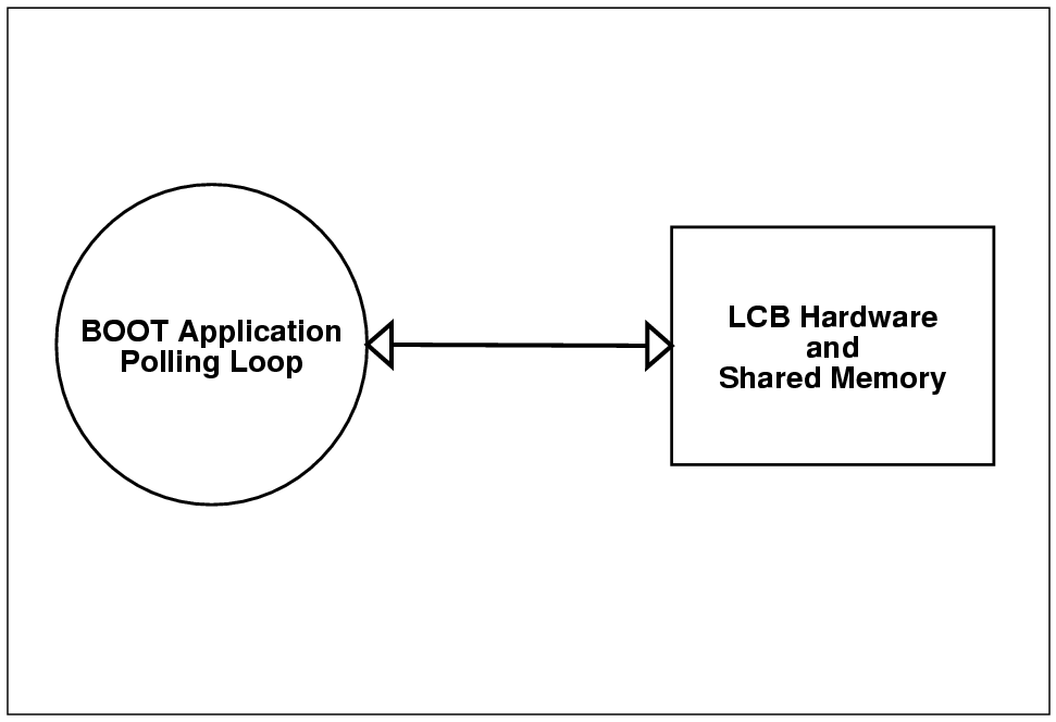
The polled mode LCBD is used by the LAT boot application when the services of a RTOS are not available. During boot the polled mode LCBD is limited to sending and receiving traffic on the event data fabric only. The polled mode LCBD will not send or receive data on the command/response fabric.
In the absence of an RTOS processing interrupts will be not be possible. Therefore the polled mode LCBD must be driven by the boot application's event poll loop. The polling interface notifies the boot application when a new response is ready for processing.
The sending interface allows the boot application to send bulk data between CPU crates on the event fabric.
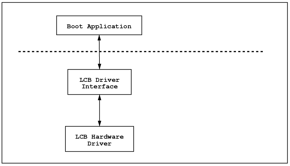
3.1. Driver Libraries
The polled mode LCBD interface presents a public, stable interface to a single user, the LAT boot application. The polled mode LCBD interface depends on the LCB hardware library ( see Chapter 1).
The Figure 3-2 below shows the polled mode LCB driver library. Note that the boot application only interacts with the public interface of the LCBD.
3.2. Driver Interface
The polled mode LCBD provides the following services:
Driver initialization.
Dispatching unsolicited LCB-to-LCB data.
Sending unsolicited packets on the LATp event fabric.
3.2.1. Driver Initialization
Before beginning operation the polled mode LCBD requires several chunks of "scratch pad" memory, which must be provided by the boot application. The required memory sizes and characteristics are shown below:
| Memory Space | LCB DMA | Size | Alignment |
|---|---|---|---|
| LCBD Handle | N/A | < 100 Bytes, fixed. | None |
| Command List | Read | Up to 4092 Bytes | 512 Byte |
| Result List | Write | Up to 4084 Bytes | 8 Byte |
| Circular Buffer | Write | 512KB up to 4MB | 1MB |
Table 3-1. polled mode LCBD Memory Attributes
The LCBD handle is used to manage the LCB.
A single command list is required to send LCB-to-LCB data on the event fabric.
A single result list is required because the LCB will generate a simple response to the bulk data transfer request.
The circular buffer is required to receive unsolicited data on the event fabric.
The function prototype for initializing the polled mode LCBD is shown below.
This call returns an initialized LCB handle. The cmdList parameter is a pointer to a memory 4KB memory chunk to use for the command list. The rstList parameter is a pointer to a memory 4KB memory chunk to use for the result list. The baseAddr parameter is the base memory address to use for the circular buffer.
At this point the LCB is completely configured. The reception of unsolicited data is enabled by calling LCB_PollStart() shown below.
3.2.2. Dispatching Results
This section leverages much of the machinery described previously for unsolicited data handling, see Section 2.5. The major difference is that the interrupt handler and callback routines are replaced with a simple polling loop.
The LAT boot application will poll the LCBD looking for new unsolicited data by calling the LCB_PollQuery() function.
When new LCB-to-LCB data is available this function returns a non-NULL LCB_msg pointer. When no data is available LCB_PollQuery() returns NULL.
Decoding the LCB_msg pointer proceeds as previously described in sections Section 2.5.2, Section 2.5.3 and Section 2.5.4. The big difference is that the decoding occurs within the polling loop, not in a user callback routine. See Section 3.3 for an example of the polled mode interface.
3.2.3. Sending Bulk Data
Sending bulk data on the event fabric is very straight forward. The maximum length of a bulk data item is 4080 bytes. Most of the discussion on sending bulk data using the ISR driver applies to the polled mode driver as well (see Section 2.4.1.2.4). The major difference is that the polled mode LCBD can only queue a single bulk transfer at a time.
The LCB_PollSend() function is used to send bulk data.
3.3. Example Driver
This sections covers examples for initializing the polled mode LCBD, for dispatching results in a polled event loop and for sending bulk data.
3.3.1. Initialization
An example of initializing the polled mode LCBD follows:
// global LCB handle
static LCB                  *lcb; // LCB handle

int initLCB() {

  int                status  =  LCB_OK;
  void            *pCmdList; // command list
  void            *pRstList; // result  list
  void           *pBaseAddr; // base address of circular buffer

  // allocate memory for the command list -- suitably aligned
  pCmdList = mallocCommandList( 4096);

  // allocate memory for the result  list -- suitably aligned
  pRstList = mallocResultList( 4096);

  // allocate memory for the LCB handle
  lcb = malloc( LCB_SizeOf());

  // assign base address for circular buffer
  pBaseAddr = LCB_CIRC_BASE_ADDR;

  // initialize the LCB handle
  status = LCB_PollInit( lcb, pCmdList, pRstList, pBaseAddr);
  if ( status != LCB_OK) {
    free(lcb);
    free(pRstList);
    free(pCmdList);
    return status;
  }

  // the LCB is now initialized, but not enabled

  return status;

}
|
3.3.2. Polled Event Loop
This section describe the polled event loop. First the reception of unsolicited data is enabled and then the driver enters an infinite loop waiting for LCB messages. As messages are found they are processed.
int eventLoop( unsigned int usrData) {

  int                 status = LCB_OK;
  LCB_msg             msg;

  // enable the LCB for receiving event data
  status = LCB_PollStart( lcb);

  if ( status != LCB_OK) {
    return status;
  }

  // enter infinite loop
  while ( 1) {

    if ( msg = LCB_PollQuery( lcb)) {
      // message found, process it.

      if ( msg->error) {
        // record/report error
        status = msg->error;
      }
      else {
        // proces the message.  The user could also make a copy of
        // the bulk data at this time.
        status = processData( usrData, msg->bulkData);
      }

      // free unsolicited data
      LCB_msgFree( msg);

    }

  // sleep, or poll other devices, etc...

  }

  return status;

}
|
3.3.3. Sending Bulk Data
This section describes sending bulk data on the event fabric.
int sendData( LCB *lcb) {

  int           status = LCB_OK;
  unsigned int  nBytes = 4000;   // number of bytes to send
  unsigned int  *data;
  short         destAddr = 0x41  // destination LATp node address
  short         proto = 3;       // LATp prototcol to use

  data = (unsigned int *)malloc( nBytes);

  // fill *data with interesting data to send

  status = LCB_PollSend( lcb, destAddr, proto, nBytes, data);

  free( data);

  return status;
}
|