B.2. Trigger Message
The structure of a trigger message is illustrated in Figure B-3.
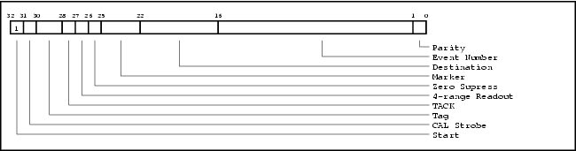
At a high level the trigger message consists of two parts: the dynamic high order 16 bits that vary from event-to-event and the low order 16 bits which are mostly static due to the slowly changing event number.
B.2.1. Trigger Mask/Config register
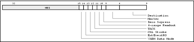
At the start of a data taking run software specifies the initial event number, initial tag and the definition of parity ( either even or odd ) in the 18 LSB of the Trigger Mask/Config register, as shown in Figure B-4.
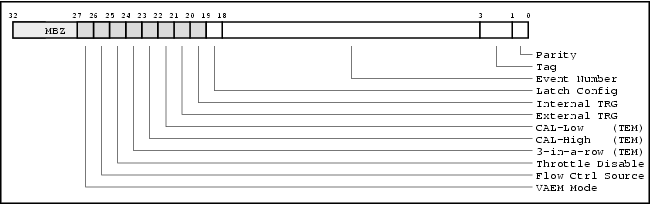
Figure B-4. Structure of the initial event number and parity definition in the Trigger Mask/Config register.
At the start of a data taking run software informs the hardware to latch the initial event number, initial tag and parity definition by transitioning the Latch Config bit (bit 19) of the Trigger Mask/Config register from 0 to 1. These parameters will be constant for the duration of the data taking run.
For each trigger message in a data taking run the LAT COMM I/O Board board will generate a monotonically increasing event number using the 15-bit event number and 2-bit tag of the Trigger Mask/Config register as the initial seed. These fields specify what the first event number will be.
On overflow the event number will wrap around to zero.
The bit labeled parity in the Trigger Mask/Config register controls whether to use even parity (bit set) or odd parity (bit clear). This allows software to force parity errors for testing purposes.
Using the Trigger Mask/Config register the LAT COMM I/O Board will construct the 16 LSB of a trigger message.
B.2.2. Options register
The dynamic component the trigger message resides in another VME register, the Options register. The Options register is mapped out in Figure B-5. These bit fields may be frequently updated by software on a per event basis.
The LAT COMM I/O Board will use this register to construct the 16 MSB of a trigger message.
The ExtEventRO bit controls whether trigger messages generated by the COMM board in response to external trigger sources will include the current values for the CalStrobe and TACK bits.
If the ExtEventRO bit is set then trigger messages generated by the COMM board in response to external trigger sources will have the CalStrobe and TACK bits cleared, i.e. a normal event read out trigger is sent.
If the ExtEventRO bit is clear then trigger messages will contain the values of the CalStrobe and TACK bits currently assigned in the Options register. Setting the ExtEventRO bit allows one to take event data by sending a naked CalStrobe trigger message – the much sought after self triggering mode.
Example B-1. Calorimeter Calibration Strobe
Consider the case of the CAL where a naked CalStrobe trigger message is used for self triggering. In this case the Options register is programmed with the CalStrobe bit set, the TACK bit clear and the ExtEventRO bit set.
The internal software trigger is then initiated, resulting in a CalStrobe trigger message. This message raises the high energy CAL trigger signal coming from the CAL front ends, which is an external trigger source. With the ExtEventRO bit set the LAT COMM I/O Board will then send down an event readout trigger message upon seeing the high energy trigger signal. This results in a regular event read out initiated by a naked CalStrobe.
If the ExtEventRO bit had been clear the LAT COMM I/O Board would have send down another CalStrobe trigger message, since the CalStrobe bit is set in the Options register.
B.2.2.1. Virtual AEM Data Mode
When the mini-GLT operates as a Virtual AEM the Virtual AEM Data Mode bit of the Options register controls the expected input data format. When set the data is expected to be in ACD event data format. When this bit is clear the data format is expected to be that of a response to a ACD command. See Appendix C for more about the Virtual AEM.