
Like SGML, XML allows you to define your own elements. In particular, elements may have attributes and they have a content model, the thing which describes how elements can be nested in other elements. An SGML language is described by a Document Type Definition (DTD). An XML language may also be described by a DTD or by the new alternative, XML Schema. It's even possible (because of the simplifications as compared to SGML) to write documents in an XML language and use them sensibly with no explicit description. No matter what method, including none, is used to describe an XML language, all XML documents must have a tree structure. There is a single root element and all other elements are its children, grandchildren, etc.
For geometry description we use a DTD called gdd.dtd. Here is an extract from it, to give you an idea of what a DTD looks like:
<!ELEMENT  composite ( addmaterial )+>
<!ATTLIST  composite
        density      NMTOKEN  #REQUIRED
        name         ID       #REQUIRED
        RGB          NMTOKENS #IMPLIED
        transparency NMTOKEN  #IMPLIED>

<!ELEMENT  addmaterial  ( fractionmass | natoms ) >
<!ATTLIST  addmaterial
        material     IDREF  #REQUIRED>
This is part of the materials-description part of the DTD. It defines an element called a <composite>. It has one or more <addMaterial> elements as children and attributes density, name, RGB (i.e., RGB components of color when displayed) and transparency. The first two attributes must be specified; the others are optional. An <addmaterial> element always has only a single nested child element, either <fractionmass> or <natoms>, and a single required attribute. Here is an extract from our geometry description using these elements:
<composite name="CsI" density = "4.51">
  <addmaterial material="Cesium">
    <natoms n="1" />
  </addmaterial>
  <addmaterial material ="Iodine">
    <natoms n="1" />
  </addmaterial>
</composite>
For a little more about XML, including references, see this Introduction. The two references I've found the most useful are the W3C reports and recommendations page and Robin Cover's incredibly comprehensive site, http://xml.coverpages.org/sgml-xml.html [Note: the URL given for Robin Cover's site in the Introduction is obsolete.]
Our XML documents have a root element called <gdd> which can have several kinds of child elements. For our purposes the most important are <constants>, <materials>, <section> and, with lower priority, <idDict>
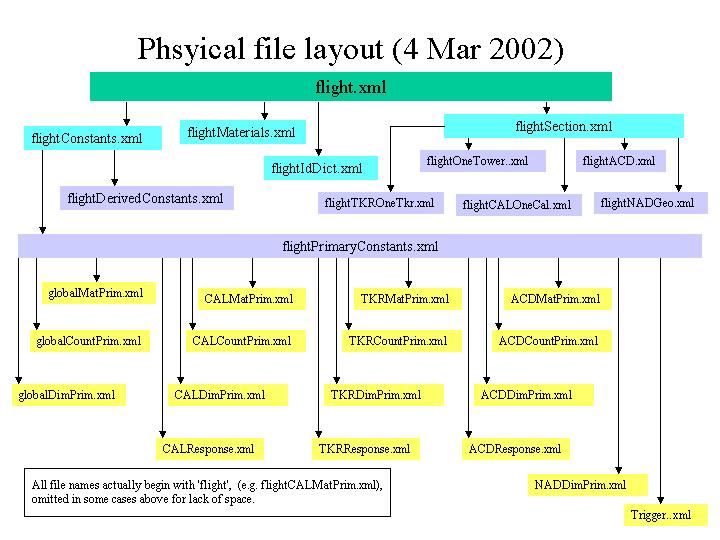
.Even for a relatively small and simple detector like GLAST the xml description runs to several thousand lines. Maintaining a single file of this size, particularly one containing information from different constituencies, is awkward, and precludes reuse of those parts of the description common to different instruments. XML inherited a (rather crude) include mechanism from SGML using external entities. An entity is just something which may contain data (i.e., characters). Each external entity is a separate physical file which gets literally included when referenced (like #include in C++). Our current physical file structure separates different subsystems from each other and also separates constants of different kinds from each other and from the definitions of shapes and their placement. The outermost file has no real content of its own; it is just a container for including other files.
Since xml files are just ascii text, any text editor will do. If you are already familiar with emacs it is preferred because of the psgml package which has an xml mode. It is already installed on the central SLAC unix system though you probably will have to modify your .emacs file to gain access to it. For other systems you can download and build psgml yourself.
There also exist much more complicated (and sometimes expensive) packages to help you edit your XML. See Robin Cover's site for the latest information. (Scroll down to the section "XML Dcoument Editing...")
| a. Syntax reminders | b. Outermost file | c. Including files | d. Materials |
| e. Simple solids | f. Positioning volumes | g. Id fields | h. Global coordinates |
NOTE: Please read this section and the following section on conventions through completely before attempting to actually write any XML.
The top file for each instrument description will have essentially the same form: a certain amount of boilerplate XML stuff, including a reference to our DTD, a list of entity definitions, followed by references to some or all of the entities defined. Physical files corresponding to the entities references will be included in the XML document. Here is most of a typical top file, the one for the flight instrument. Only some of the entity definitions have been omitted.
<?xml version="1.0" ?>
<!-- $Header: /nfs/slac/g/glast/ground/cvs/xmlUtil/xml/flight.xml,v 1.17 2002/01/29 21:40:19
jrb Exp $ -->
<!DOCTYPE gdd SYSTEM "../gdd.dtd"
[
<!-- Define entities for included files -->
<!ENTITY globalMatPrim SYSTEM "flightGlobalMatPrim.xml">
<!ENTITY globalCountPrim SYSTEM "flightGlobalCountPrim.xml">
<!ENTITY globalDimPrim SYSTEM "flightGlobalDimPrim.xml">
<!ENTITY CALMatPrim SYSTEM "flightCALMatPrim.xml">
<!ENTITY CALCountPrim SYSTEM "flightCALCountPrim.xml">
<!ENTITY CALDimPrim SYSTEM "flightCALDimPrim.xml">
.
.
<!ENTITY NADDimPrim SYSTEM "flightNADDimPrim.xml">
<!ENTITY NADGeo SYSTEM "flightNADGeo.xml">
<!ENTITY Trigger SYSTEM "flightTrigger.xml">
<!ENTITY Derived SYSTEM "flightDerivedConstants.xml">
<!ENTITY Primary SYSTEM "flightPrimaryConstants.xml">
<!ENTITY idDict SYSTEM "flightIdDict.xml">
<!ENTITY Materials SYSTEM "../materials.xml">
]
>
<gdd CVSid="$Id: flight.xml,v 1.1.1.1 2002/03/04 22:09:35 jrb Exp $"
DTDversion="2.0" >
<constants>
<version major="0" minor="0" />
&Primary;
&Derived;
</constants>
&Materials;
&idDict;
§ion;
</gdd>
The entity definitions above effectively give symbolic names to physical files. As in this example, the symbolic names should be generic, but file names should start with the name of the instrument in those cases (practically all) where the content of the file is specific to a particular instrument. For example, all instrument descriptions will require derived constants. The entity should have symbolic name Primary and the physical file will be named something like instrnamePrimary.xml When possible stick to the entity names now in use in flight.xml.
To include a file mentioned in an entity definition, simply use its symbolic name with the appropriate syntax: precede with ampersand (&) and follow with semi-colon (;) like this:
&Primary;
This is one place where we might be able to get away with a single physical file to be used for all instruments. If this file (currently flightMaterials.xml, but name will change if it is to be used as a universal materials file) does not have a material you need, you'll have to talk to the Core group about getting it added.
If you need several materials unique to your instrument, you might just want to maintain your own file. You should do it in the same style as the standard file flightMaterials.xml. In particular,
The following extract from the standard materials file illustrates how you describe atomic elements, how you make a material consisting of a single atomic element, and how you make a true composite material. Densities are always in units of g/cm3 and atomic weights are in g/mole.
<Some atomic elements -->
<element name="Silicon"
	 symbol="Si"
	 z="14"
	 aweight="28.088"
	 />

<element name="Oxygen"
	 symbol="O"
	 z="8"
	 aweight="15.999"
	 />

<element name="Aluminum"
	 symbol="Al"
	 z="13"
	 aweight="26.892"
	 />

<!-- Some single-element materials -->
<!-- Standard silicon; let its name just be its atomic symbol -->
<composite name="Si" density="2.4">
   <addmaterial material="Silicon">
     <natoms n="1" />
   </addmaterial>
</composite>

<!-- We use aluminum in several place, potentially of different densities -->
<composite name="Al" density="2.702">
  <addmaterial material="Aluminum">
    <natoms n="1" />
   </addmaterial>
</composite>

<composite name="Al_3lb" density="0.0481">
  <addmaterial material="Aluminum">
    <natoms n="1" />
   </addmaterial>
</composite>

<composite name="Algrid" density="2.702">
  <addmaterial material="Aluminum">
    <natoms n="1" />
   </addmaterial>
</composite>

<!-- True compounds, one using <natoms> and one using <fractionmass> -->
<composite name="CsI" density = "4.51">
  <addmaterial material="Cesium">
    <natoms n="1" />
  </addmaterial>
  <addmaterial material ="Iodine">
    <natoms n="1" />
  </addmaterial>
</composite>

<composite name="Tkr_wall" density = "2.54">
  <addmaterial material="Carbon">
    <fractionmass fraction="3.30" />
  </addmaterial>
  <addmaterial material ="Iron">
    <fractionmass fraction="0.16" />
  </addmaterial>
</composite>
It is not necessary to normalize fraction values in <fractionmass> elements to add up to 1.0, as can be seen in the last composite defined above, nor do the values of n in <natoms> elements have to be integers.
Definitions of simple solids then specify a material with a materialREF attribute whose value is the name of a primary constant, which in turn refers to one of the composites. See an example of such a primary definition and its use in the next section.
    <box name="diodeL"
         sensitive="intHit"  detectorTypeREF="eDTypeCALDiode"
         XREF="diodeX"
         YREF="diodeLY"
         ZREF="diodeZ"
         materialREF="diodeMat" />
Note that most of the attributes of the <box> element end in REF. The values are all strings which must be defined elsewhere in the <constants> part of the file, like this:
  <prim name="diodeX" value="0.30"> Depletion depth of diode Si
</prim>
  <prim name= "diodeLY" value= "14.5"> Width of large diode Si
</prim>
  <prim name= "diodeSY" value= "2.4"> Width of small diode Si
</prim>
  <prim name= "diodeZ" value= "10.5"> Height of diode Si
</prim >
For the most part dimensions of simple solids will be primary constants, that is, constants which come from external sources, such as system designers, rather than being computed. You can write the XML to define simple solids first, then, after doing a search of previously-defined constants, go back and add new primary constants for dimensions if necessary.
In order to keep the full geometry consistent, it is vital that all primary constants be independent of each other. No new constant should be added if the value can be computed from existing constants using standard arithmetic operations.
Material names are also references, in this case to a primary constant whose definition looks like this:
  <prim name="diodeMat" value="Si" type="string" uType="mat">Diode Material
</prim>
The value of the constant, here Si, must also exist as a material in the <Materials> part of the XML document.
For simulation it is best to build up the detector description hierarchically; e.g. thin boxes of several materials go to make up a tracker tray, tracker trays are stacked up to make a single-tower tracker, a tracker + a calorimeter make up a tower, etc. Our XML language provides two ways to assemble volumes: stacking (<stackX>, <stackY> or <stackZ>) and <composition>. The stack elements allow the child volumes to be stacked along a particular axis, as is done to create a single tracker tray. <composition> allows arbitrary positioning. Another difference is that <composition> requires that an envelope volume (usually made of vacuum) be specified in the XML. For the stack elements the code interpreting the XML is responsible for computing an envelope volume if it wants one. The detModel package takes care of this for typical applications. For a precise description of <composition> and the stack elements see gdd.dtd. For examples see flightCALOneCal.xml. Note that while dimensions of volumes are usually primary constants, offsets used to position volumes often have to be derived. An XML version of standard arithmetic has been defined for this purpose. The syntax is reasonably self-explanatory. See gdd.dtd for definitions of elements <add>, <minus>, <quo>, <mul>, <uminus>, <max>, <half>, <const> and <refer>. For examples of their use see flightDerivedConstants.xml.
Volumes need to be identified for various purposes. Logical volumes have unique names, but there may be multiple physical copies of a single logical volume. In order to uniquely identify each physical volume, the XML description allows the assignment of values for one or more identifier fields (<idField>) at each positioning step. Here is part of the XML used to define a CsiElement as a composition of a crystal and 4 diodes:
    <composition name="CsIElement"  envelope="CsIElementEnv">
      <posXYZ volume="CsIDetector">  <!-- centered in envelope -->
        <idField name="fCALCellCmp" value="eXtal" />
      </posXYZ>
      <posXYZ volume="diodeS"
              XREF="diodeNegXOffset"
              YREF="diodeSYOffset"
              ZREF="diodeZOffset"
        >
        <idField name="fCALCellCmp" valueREF="eDiodeMSmall" />
      </posXYZ>
      <posXYZ volume="diodeS"
              XREF="diodePosXOffset"
              YREF="diodeSYOffset"
              ZREF="diodeZOffset"
        >
        <idField name="fCALCellCmp" valueREF="eDiodePSmall" />
      </posXYZ>
Values for idFields always resolve to unsigned integers but in most cases, as is shown above, they are assigned using the valueREF attribute rather than value. Symbols for id field values should be defined in the <primary> part of <constants>. The values in the example above are defined in flightCALCountPrim.xml. The identifier for a volume is the concatenation of id fields assigned to it and to all its parent volumes. For more about this, see the first 4 or so slides from this presentation. It's old enough that it might not be correct in every detail, but fundamentally the scheme described there is still the one that's used.
Constraints on id fields - which idFields may follow which and what values a given idField can take on - are described in a structure known as the id dictionary. See xmlGeoDbs/xml/flight/flightIdDict.xml for an example. We expect and hope that the hierarchical structure of the description will not vary significantly from one instrument to another. Roughly speaking, the nesting structure should be the same but different instruments may be "missing" certain components. If this is the case, we should be able to use a common id dictionary for all instruments. In any case, the flight id dictionary and the assignment of idFields in the flight description should be used as models for other instruments. See also this document describing identifiers for active components of the instrument and how they relate to (Steve) Ritz conventions.
In order to establish the proper origin for the detector it will probably be necessary to make one last translation in z. You can see one method of doing this in flightSection.xml. Here all the top-level components of the simulation (grid pieces, the towers, ACD planes, thermal blanket, spacecraft...) are positioned so that z=0 is at the front plane of the grid.
The LAT may be a small instrument by HEP standards; nonetheless the XML description for the flight instrument is substantial. Over 30 physical files (plus one for the dtd) make up the XML document. At last count it had over 2100 XML elements (things in < >), including about 700 each primary and derived constants. It's no small matter to keep track of everything! Please keep the following techniques and conventions in mind.
There should be no floating point constants other than rotation angles of 90.0 or 0.0 in volume definitions or in the positioning of volumes; use references to primary or derived constants instead. Counts (e.g., number of CAL layers to be stacked) are also normally references, except within the id dictionary definition in a case like the following:
    <field name="fCALLog" >
      <vMinMax min="0" maxREF="maxLog" />
    </field>
Several somewhat fuzzy rules can be inferred from constant names currently in use:
Every constant with a name must also have a descriptive comment. These are not comments in the usual programming language sense of something solely for the human reader, ignored by the processor. XML has this sort of comment (text bracketed by <!-- and -->) but what we're concerned with here is text which is available to the XML parser because it is content for an XML element. For primary constants, the text follows the opening tag. Other constants (element type <const>) may have as part of their content an optional <notes> element which in turn has text content. Every named <const> should have a <notes> element. All these comments can then be automatically extracted and nicely formatted into html so that anyone in the collaboration can see what the constants mean and whether they seem reasonable.
Comments for derived constants should explain what they're for and something about the derivation if it's complex (rarely the case). Since values for primary constants are often handed down from somewhere else, it can be useful to reference the document they came from, if any. If a constant has changed value or was newly added, the date at which this happened can be mentioned.
Physical files unique to a particular instrument should be in a subdirectory of xmlGeoDbs/xml named after the instrument and should begin with the instrument name, for example flightCALDimPrim.xml. The same capitalization scheme is used here as for constant names (capitalize all but the first "word" within the name except for acronyms, which are all caps). Files containing primary constants have a very specific form:
[instr][subdetector][constType]Prim.xml
"subdetector" can be any of ACD, CAL, NAD, TKR or global. "constType" is one of Mat, Count, or Dim.
Filenames for derived constants look like
[instr]DerivedConstants.xml
or[instr][subdetector]Derived.xml
If possible, file names for other instruments should be analogous to those used for the flight instrument, but with a different prefix. See the files in the directory xmlGeoDbs/xml/flight before inventing any new names for your instrument.
There are some tools available which will diagnose certain kinds of problems with ill-formed or syntactically-correct but preposterous descriptions.
If you use psgml mode within emacs to edit xml files, get in the habit of using the sequence C-c / to insert the end tag (e.g. </primary>). It saves typing, but, more important, it will let you know if you haven't nested elements the way you thought, left off a closing quote, etc.
When your editing is complete you can run any of several programs using Xerces to check the syntax of your new file, such as test_Gleam.exe or test_GlastSvc.exe. Be sure that the appropriate job options parameter has been set to point to your new geometry description files. These programs will print out line and column number of the first syntactical problem encountered.
In case you don't have an installation of Gleam handy or would just prefer to use a more modest tool, you can run one of the sample programs supplied by Xerces and get identical diagnostic messages. These programs, such as DOMCount, which uses the DOM parser to parse the document and returns a count of the elements, can normally be found in $XMLEXT_DIR/bin. ($XMLEXT_DIR is defined when you do a CMT setup for the XMLEXT package or for some other package using it.)
NOTE: The current public GLAST Linux installation of Xerces at SLAC does not include these diagnostic programs. A more complete installation can be found at ~jrb/xerces/xerces-c-src1_7_0/. You'll need to add ~jrb/xerces/xerces-c-src1_7_0/lib to your LD_LIBRARY_PATH; then you may run the programs as described, substituting ~jrb/xerces/xerces-c-src1_7_0 for $XMLEXT_DIR.
If your document is OK you'll get output something like this:
jrb@noric05 $ $XMLEXT_DIR/bin/DOMCount flight.xml
flight.xml: 451 ms (2374 elems).
If you're not so lucky, output might look like this (still not too bad since you're told where and what the problem is):
jrb@noric05 $ $XMLEXT_DIR/bin/DOMCount flight.xml

Error at file
/a/surrey10/g.glast_users/glground/jrb/G4Gen/xmlGeoDbs/v1r5/xml/flight/flightCALOneCal.xml,
 line 9, char 16
  Message: Attribute 'XBREF' is not declared for element 'box'

Errors occured, no output available
or, worse, like this:
jrb@noric05 $ $XMLEXT_DIR/bin/DOMCount flight.xml

Error at file
/a/surrey10/g.glast_users/glground/jrb/G4Gen/xmlGeoDbs/v1r5/xml/flight/flight.xml,
line 70, char 7
  Message: ID attribute 'CsILenght' was referenced but never declared

Errors occured, no output available
Line 70, character 7 is just the end of the top file flight.xml, which is not very helpful. All you can do in this case is look for occurrences of CsILenght and realize that this is undoubtedly a misspelling of CsILength.
There is a whole auxilliary package, detCheck, devoted to verifying the content of an XML description. To use it, first just check it out from CVS in the usual fashion and build it. Up to date instructions for the three programs described below can be found in the package mainpage.h. In case of conflict, the instructions in the mainpage supersede what follows.
The program test.exe checks for overlapping volumes. It will check for overlaps among "siblings" (volumes positioned inside the same parent) and for compositions will also check that each child volume is within the envelope specified in the XML description. It takes up to three arguments. The first is the input XML file. The second is the output file (defaults to standard output) and the third is a verbose flag. If there is a third argument, the flag is true; otherwise it's false. You must supply an output file in order to ask for the verbose output (you wouldn't want it just on your screen - trust me). Here is a typical invocation using glastpack, where the environment variable newModelDir has been set to the directory containing the XML source to be checked, flight.xml:
glastpack.pl run detCheck test.exe $newModelDir/flight.xml overlap.txt verbose
If the file passes, the output looks something like this:
Checking composition volume 0 named ACDTop
Checking stack volume 0 named ACDTopSupport
Checking stack volume 1 named ACDXSideSupport
Checking stack volume 2 named ACDYSideSupport
Checking composition volume 1 named CALBottomFrame
Checking stack volume 3 named CALLayer
Checking stack volume 4 named CALLayerYMeas
Checking stack volume 5 named CALLayers
Checking composition volume 2 named CALTopFrameLowerVol
Checking composition volume 3 named CALTopFrameUpperVol
Checking composition volume 4 named CsIElement
Checking composition volume 5 named LAT
Checking stack volume 6 named SiLadders
similar lines omitted
Checking stack volume 31 named sideTileRowY3
Checking composition volume 16 named solarPanel
Checking stack volume 32 named towerRow
Checking stack volume 33 named trayBot
more omitted
Checking stack volume 40 named trayTop
Congratulations!  No overlaps found.
For each volume, the test program checks (among other things) for overlaps among its immediate children. If an overlap is found in verbose mode it will print out two coordinates for each of the overlapping volumes. The first is the vertex of the box with least x, y and z coordinates and the second is the diagonally opposite vertex. (Incidentally, this tells you how big detModel thinks each such volume is. Simple boxes always have dimensions explicitly specified. Following the output for all such overlapping pairs within the mother volume being checked is a list of all the child volumes, associating numbers with names, like this:
Checking composition volume 4 named LAT
Working on the volume called LAT
Overlapping volumes.  Vertex coords are:
1st volume:  (-749, -749, -251.825) and (749, 749, 640.625)
2nd volume:  (-817.775, -817.775, -1651.2) and (817.775, 817.775, -251.2)
Overlap between child volumes #2 and 28
Found two children of LAT which overlap. max and min coordinates of the two volumes are given. "Overlap" means intervals in each of dimensions X, Y, Z must overlap. In this case the 2nd volume contains the first in X and Y; there is only a small intersection of the Z intervals.
Overlap check failed in volume #27, Composition volume #4 LAT
Summary: check of LAT failed. Following is a list of all children so that volume numbers above (2 and 28) may be correlated with names.
Child volume #0 is ACDTop
Child volume #1 is ACDTopSupport
Child volume #2 is allTowers
Child volume #3 is ACDYSideSupport
Child volume #4 is ACDYSideSupport
Child volume #5 is ACDXSideSupport
Child volume #6 is ACDXSideSupport
Child volume #7 is LATGridFlangeLong
Child volume #8 is LATGridFlangeLong
Child volume #9 is LATGridFlangeShort
Child volume #10 is LATGridFlangeShort
Child volume #11 is LATGridWebLong
Child volume #12 is LATGridWebLong
Child volume #13 is LATGridWebShort
Child volume #14 is LATGridWebShort
Child volume #15 is TileYSide
Child volume #16 is TileYSide
Child volume #17 is TileXSide
Child volume #18 is TileXSide
Child volume #19 is sideRibbonsY
Child volume #20 is sideRibbonsY
Child volume #21 is sideRibbonsX
Child volume #22 is sideRibbonsX
Child volume #23 is blanketTop
Child volume #24 is blanketYSide
Child volume #25 is blanketYSide
Child volume #26 is blanketXSide
Child volume #27 is blanketXSide
Child volume #28 is spacecraft
Child volume #29 is solarPanel
Child volume #30 is solarPanel
This complets output of check of LAT volume. Now move on to check remaining volumes.
Checking stack volume 5 named SiLadders
Checking...
..so allTowers (child #2) is running into spacecraft (#28). We would expect them to overlap in X and Y, but not in Z, so the computation of the z-offset used to position one or the other within LAT is wrong.
The program constsDoc.exe may be used to generate an html file listing all the primary and derived constants, like this one for the most recently-released version of xmlGeoDbs. You call it like this:
constsDoc.exe XML-infile html-outfile
An invocation via glastpack, assuming the same input as above, would look like this:
glastpack.pl run detCheck constsDoc.exe $newModelDir/flight.xml myConsts.html
The program summary.exe may be used to generate an html file containing two tables summarizing materials used in the model: one with a row per material, the second with a row per logical volume. See for example the output for the latest tag. summary.exe is invoked as follows:
summary.exe< aPath/myGeoInput.xml anotherPath/mySummary.html [topVolume [choice-mode] ]
Last modified: